
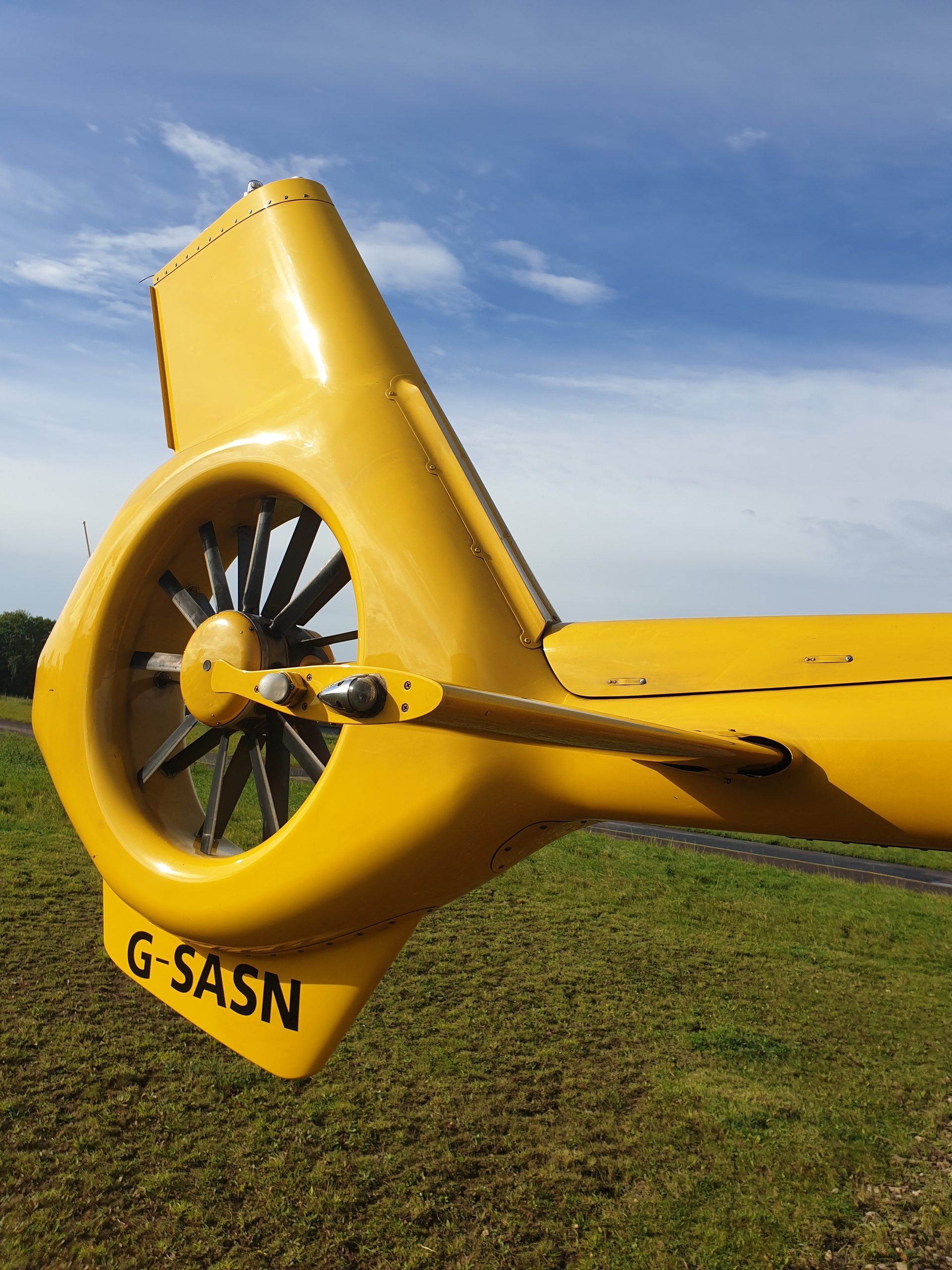
The H145 helicopter is a very stable but controllable aircraft and in its latest D3 form, a very smooth ride. But take a look at the tail and there are a lot of aerodynamic tweaks that have been added to help make it a pleasant aircraft to fly.
In this article we look at the areas of the tail structure that have been tweaked and explain why these features have been added. We also look at some similar aircraft to show how other aerodynamic nudges have been used to correct handling problems.
We will try to explain the aerodynamic effects in simple terms but if you need more information we can highly recommend the Ray Prouty books which bring together his articles from Rotor and Wing and Vertiflite magazines:
- Helicopter Aerodynamics – Volume 1 – Ray Prouty
- Helicopter Aerodynamics – Volume 2 – Ray Prouty
- Helicopter Aerodynamics – Volume 3 – Ray Prouty
We have looked at the H145 autopilot in an earlier article (Automated Take Offs) but now we are going to get a little more under the hood. Let’s get stuck in.
Contents
H145 Aerodynamic Tweaks
Before we go any further, what do we mean by aerodynamic tweaks? Surely tweaks are unnecessary in this modern age of CFD and computer-aided design. Don’t the designers get it right before the first part is even made? Of course not! Helicopter aerodynamics is a dark art with many mysteries still to be uncovered. Many bizarre effects are only uncovered in live flight test requiring the design to go back to the drawing board to design a fix.
These fixes can usually be spotted as extra bits of metal tacked on or indeed removed. The more complex a part ends up looking, the more likely it needed some tweaking its design life.
So what tweaks are there on an H145?
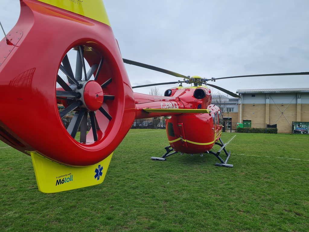
Vertical stabiliser – a flat rear end
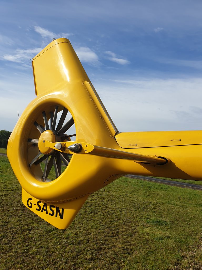
The H145 has a fenestron in place of a conventional tail rotor. A fenestron, ducted-fan or fan-in-fin is a not just the spinning multi-bladed rotor. The duct in which it operates is a significant part of the design. The airflow through that duct provides a substantial part of the total thrust at very high and very low thrust settings. This is part of the reason why fenestron power response is non-linear and can catch out pilots brought up on conventional rotors. We will save that for another article!
In any case, the need for a duct means the fenestron requires quite a thick structure laterally.
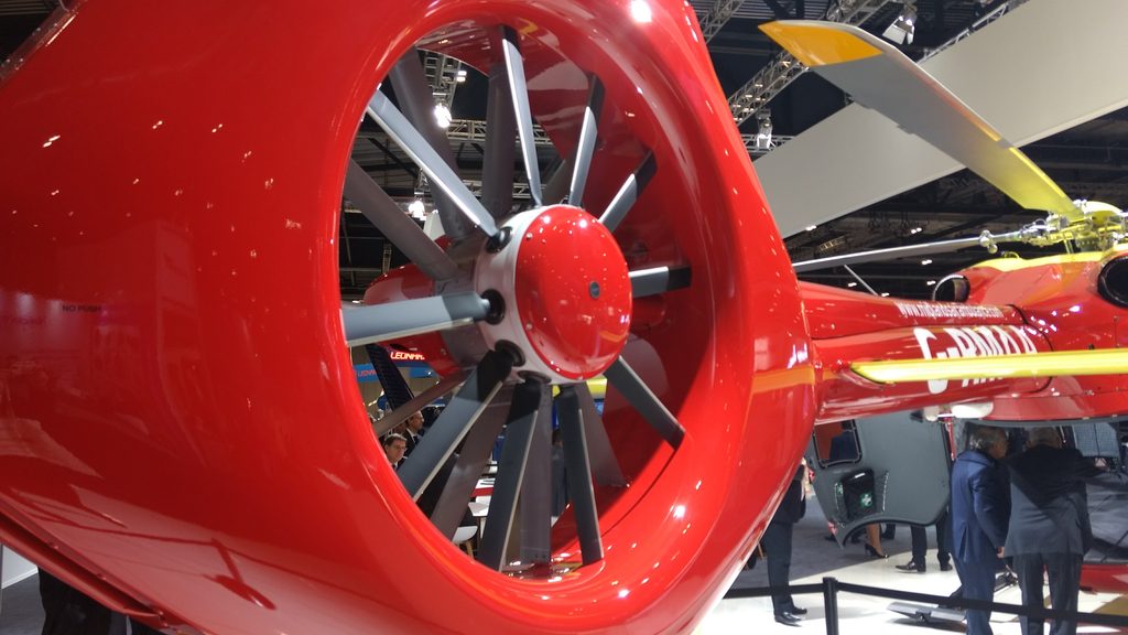
We want to streamline airflow around our fat tail tail end so we add a nice taper to the back of the fin. Or perhaps not…
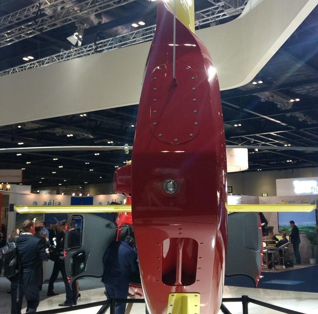
It’s been chopped off. Surely a blunt tail is more draggy than a nice faired tail end? More on this later.
Vertical stabiliser – Stall Strip
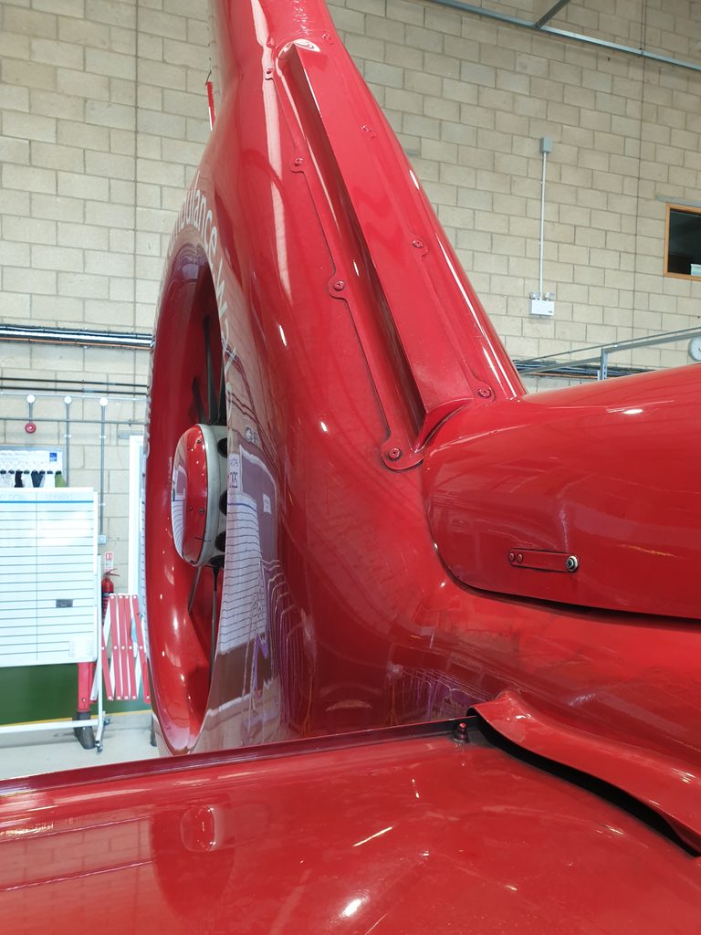
Looking at the front of the vertical stabiliser, a rather ugly bolted on Toblerone has been stuck on. Note it is only ahead of the fenestron fairing and is not on the upper cambered tail fin leading edge.
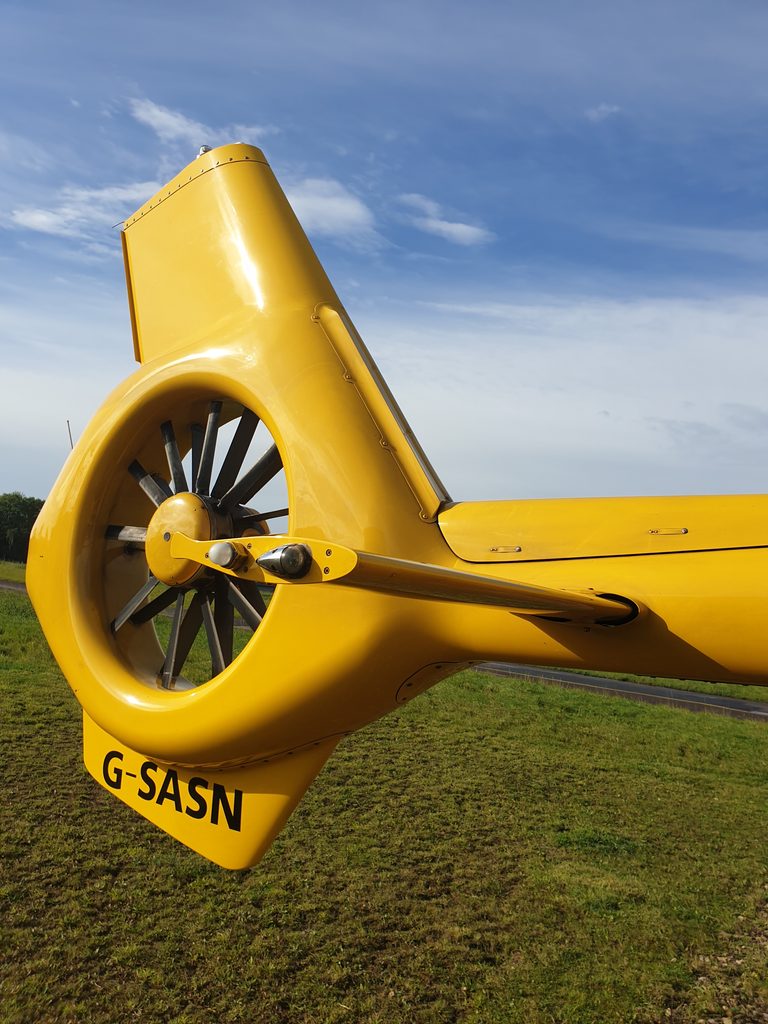
This particular feature is notably absent from the very similar tail of the H135. What is going on with the aerodynamics of the H145?
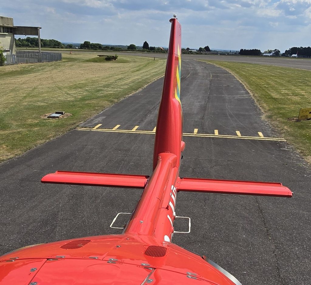
More on this later. What other tweaks are there?
Horizontal stabiliser – Gurney Flaps
Take a close look at the H145 horizontal stabiliser and you will notice a little flap of metal sticking up along the rear edge. It’s not there to stop water dripping on you when doing a pre-flight inspection, nor is there as a means of increase strength like a rib between spars in traditional airframe building methods.
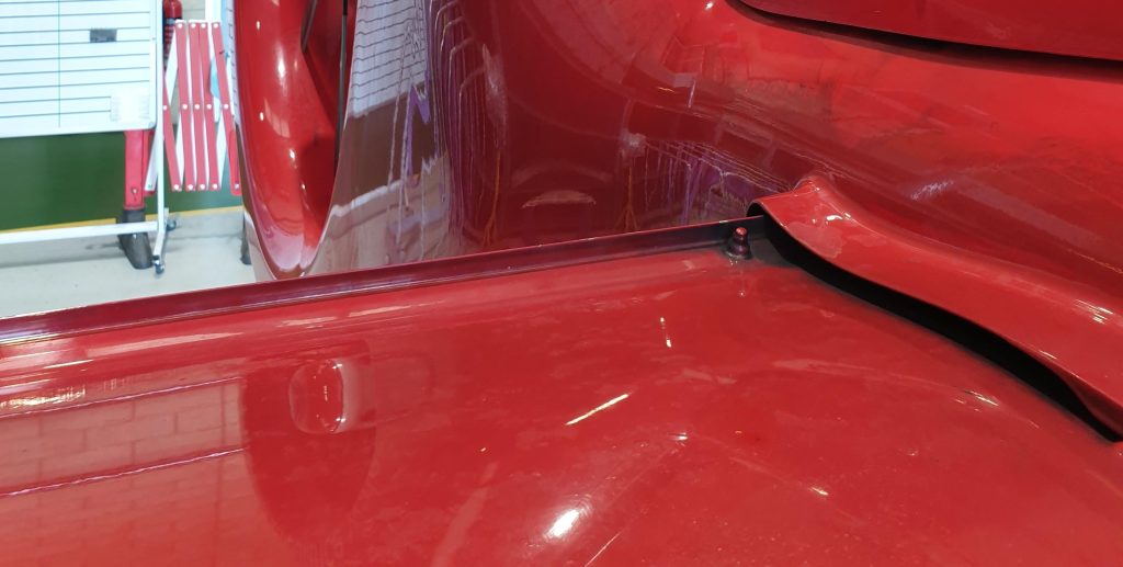
The tailplane on the H145 is similar to many helicopter horizontal stabilisers in that it is an upside-down aerofoil. Lift is generated downwards to balance the forces on the helicopter in forward flight. The upper surface is the “high” pressure side, the lower surface is the “low” pressure side. The Gurney Flap is on the high pressure side at the back of the aerofoil (like flaps on a conventional aeroplane). Look back at the H135 and you will see similar Gurney Flaps on the horizontal stabiliser.
But there are more Gurney Flaps on the H145!
Vertical stabiliser – more Gurney Flaps!
A look up at the rear of the vertical stabiliser on the H145 shows another Gurney flap along the back of the cambered part of the upper fin.
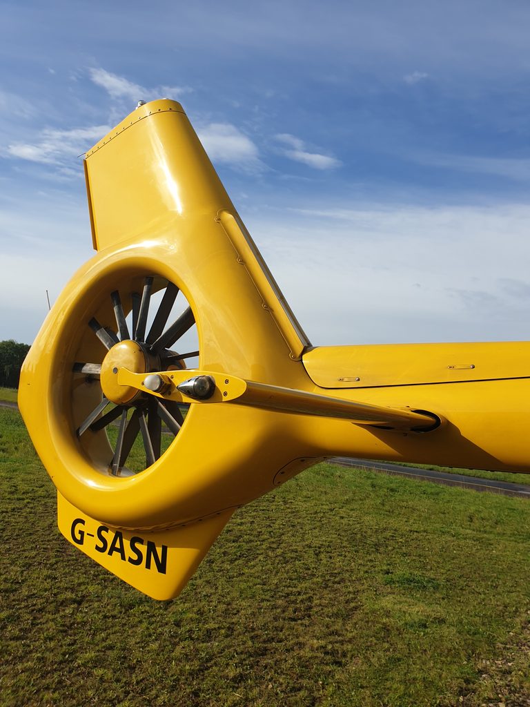
However, think about this for a moment. It’s on the right side of the fin. The main rotor of the H145 turns anti-clockwise meaning the tail fin and fenestron need to generate a lift force to the right to generate a balancing anti-torque effect. This gurney flap is on the low pressure side of the fin.
That goes against the conventional wisdom of gurney flaps which we will explain later.
The tweaks
So we have four aerodynamic tweaks we need explore on H145:
- Horizontal stabiliser
- Gurney flap along the rear edge
- Vertical stabiliser
- Gurney flap on the rear edge
- Blunt rear end
- A triangle strip forward of the fenestron
Before we dig into the reasons for the tweaks let’s look at what gurney flaps are.
Gurney flaps
Gurney flaps were invented by Dan Gurney, a racing driver. It has nothing to do with flaps holding bodily fluids on a mortuary gurney as some pilots may have been told!
For really fast cars you need loads of downforce to get more grip on the road. For this wings are placed on either side of racing cars.
Racing cars
Gurney, without any rigorous aerodynamic theory to back it up, reasoned that a “dam” at the back of the wing on a racing car would increase the pressure in front of the dam as so increase the downforce.
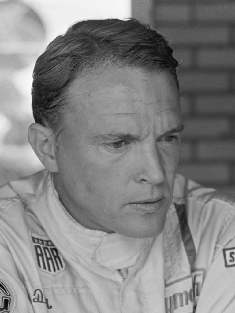
After retiring from racing and taking up management of a racing team, he experimented with flaps along the rear edge of his wing on his driver’s car (passing off the modification as a means of reduced damage!) and found it was very effective. It was actually too effective, hugely increasing down force on the rear wing, leading to understeer. A similar flap was put on the front wing too to balance the downforce front to back.
Experimental testing
Subsequent testing by aerodynamicists verified Gurney’s results. Through wind tunnel testing it was shown that a gurney flap created a vortex along the trailing edge of the aerofoil.
As shown in the diagram below, the vortex is generated at the rear of the wing behind the gurney flap. It increases the flow over the rear of the “suction” side of the aerofoil. It also increases the pressure on the pressure side of the wing at the rear.
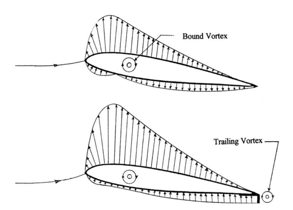
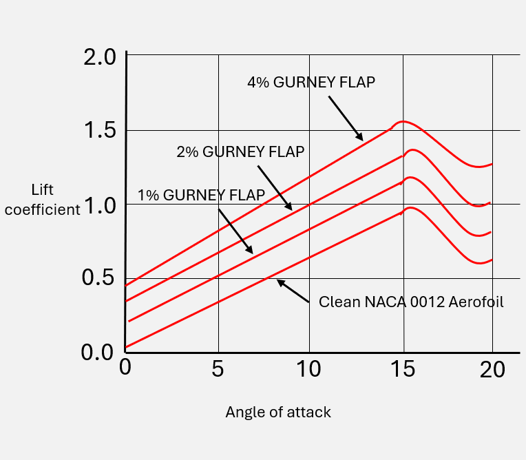
These 2 effects combined, lead to the Gurney Flap providing several positive results as shown in the chart below, extracted from Helicopter Aerodynamics Volume II:
- An increase in coefficient of lift at the same angle of attack
- Lift at zero angle of attack
- An increase in the slope of the lift curve – the horizontal stabiliser is equivalent to the chord being increased by 1.5 times the height of the flap
What about drag?
But what about drag? Surely a big fence along the back of an aerofoil dramatically increases drag? Well, no actually.
Provided, the Gurney Flap height is less than the boundary layer thickness over the aerofoil, the actual drag penalty was minimal. Experiment tests on simple aerofoils have shown the boundary layer over an aerofoil is approximately 2.5% of the chord, so provided the Gurney Flap is smaller, the drag penalty is minimal.
So gurney flaps are a simple and effective way to modify the aerodynamics of an aerofoil without a complete redesign on the whole aerofoil profile.
H145 horizontal stabiliser – Gurney Flaps
So back to our gurney flaps on H145. The rear horizontal stabiliser has Gurney Flaps on both sides of the tail boom.
The use of gurney flaps in the H145 could be for one of two reasons:
Increase in downforce required
The flight envelope of a helicopter is quite varied with respect to the demands placed on the horizontal stabiliser. It has to work in conditions varying from about negative 25 degrees angle of attack in an autorotation and positive 15 in a high power climb. It is difficult to prevent the tailplane stalling in the high power climb.
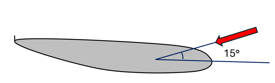
Whilst the stall angle of bank is similar with a Gurney Flap, the total lift can be increases for the same size aerofoil allowing the designers to tweak the aerodynamics of the aerofoil without a complete re-design.
Change the effective incidence
The additional of a gurney flap also changes the effective incidence of the aerofoil by modifying the lift at zero angle of attack. According to Prouty, this occurred on the Bell 407 when flight test revealed the tailplane needed to be moved but it was too difficult to change in the design. A Gurney Flap fixed the problem and that may have been the case too on H145.
We have another Gurney Flap to look at.
H145 vertical stabiliser – Negative Gurney Flap!
The Gurney Flap on the vertical fin, needs a little more consideration.
If you look at the tail of an AS350, there is Gurney Flap on the vertical stabiliser. It’s on the right, which on an AS350, with a clockwise rotor, is the pressure side of the aerofoil. The Gurney Flap increases the coefficient of lift and makes the vertical flap more effective.
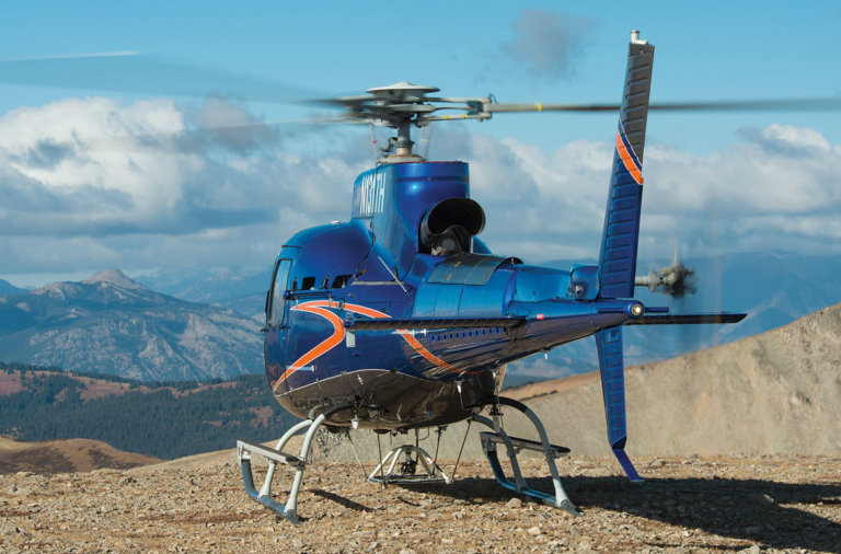
But now look at the H145 tail. The Gurney Flap on the tail fin is on the right side as well. But this is the “suction” side of the aerofoil. Should the Gurney Flap not be on the other side to improve the lift from the tail. Why would you want to make the lift coefficient worse?
Lateral-directional stability
To explain why a designer might want to reduce the effectiveness of a vertical stabiliser, we need to dip into the topic of lateral-directional stability. This topic is much more complex than the longitudinal stability of the helicopter (which is complex enough already). For a full treatment of the topic, refer to Eric Fitzpatrick’s epic tome on flight test of helicopters – Helicopter Test and Evaluation.
Let’s try to put this simply!
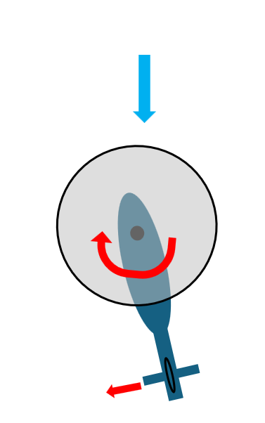
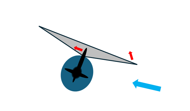
A helicopter in forward flight generally wants to be directional stable in yaw and laterally stable in yaw. The stability in each respect can be described in simple terms as the “weathercock effect” and the “anhedral effect” respectively.
Weathercock effect
If the aircraft is disturbed in yaw, we want the aircraft to correct that disturbance by reducing the asymmetry. Think of a dart being thrown. We want the pointy bit to go where we throw it! Of course, that is also like a weathercock being blown by the wind, hence the name.
On a helicopter, the stabilising force is provided by the tail fin and tail rotor. Fin area above and below the vertical centre of pressure add to the effect.
Anhedral effect
If the aircraft is disturbed in roll, we want the aircraft to correct that disturbance and roll back.
On a helicopter, the flapback effect of the main rotor and vertical area of fin and fuselage above the centre of pressure create a righting force. Fuselage and fin area below the centre of pressure act in act in the opposite way.
Balance of stability
The designers need to carefully balance directional and lateral stability.
If directional stability dominates, the aircraft could be difficult to control out of wind in the hover without large pedal inputs due to a strong weathercocking effect. In a turn in forward flight, if directional stability is much strong that the anhedral effect, the aircraft could enter a spiral descent.
If lateral stability is much stronger than directional stability, the aircraft with roll strongly back to level. Combined with weak directional stability, this can lead to the aircraft rolling the opposite way before rolling back. The rolling side to side is called Dutch Roll and the relative strength of directional and lateral stability can effect whether the Dutch Roll is a problem or not. Try an H145 without SAS at close to limiting speed of 110 kts. There will definitely be some Dutch Roll waiting for you!
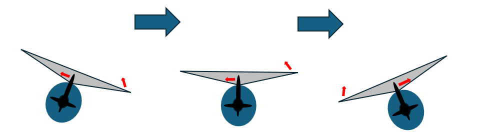
Since main rotor flap back is a key component of lateral stability, more power through the rotor leads to a stronger Dutch Roll effect. This can be noted on an H145 when comparing the handling between 80 kts and 120 kts. Even with the Autopilots engaged in ATT mode, a slight wobble can be noted at 120 kts.
So what about the flap!
So getting back on topic, we have seen that excessive fin area above the centre of pressure can lead to increased “anhedral effect” which might cause a Dutch Roll. This is likely what was found on the H145.
The addition of a Gurney Flap on the “suction” side of the tail fin has the exact opposite effect to a conventional Gurney Flap on the other side:
- Maximum lift is reduced
- Effective chord of the vertical fin is reduced
So rather than redesign the whole vertical fin to make it shorter or of smaller chord, a Gurney Flap was added on the “wrong” side to correct the problem.
Gurney Flaps are truly versatile “fixes” – we will look at one more usage in a little while.
H145 Vertical Stabiliser – flat rear end
Now returning to our tweaks, we can look at the blunt rear end next. As we briefly discussed earlier, logically you would expect an aerodynamic shape to smoothly merge to a fine point to profile the lowest drag and most efficient aerofoil. As an example look at how the back end of the H145 fuselage smoothly transitions to the tail boom and round the rear doors. Why is the fenestron fairing got such a blunt rear end then?
Airflow breakaway
The problem with a smooth transition round the back of a thick wing or fuselage section is that air just cannot get all the way around the corner. In accordance with Bernoulli, the airflow has accelerated around the the thick object. When it tries to follow the wing or fuselage all the way around to the trailing edge, it sometimes cannot and it breaks away. This leads to a change in forces over the surface.
For a vertical surface on a helicopter, this breakaway of the airflow manifests as a change in the yaw forces and the pilot needs to make inputs to correct them. The airflow might then break away from the opposite surface, to a need for a control reversal by the pilot.
The pilot might describe this as a “squirrelly” or unstable feeling. So how to correct it?
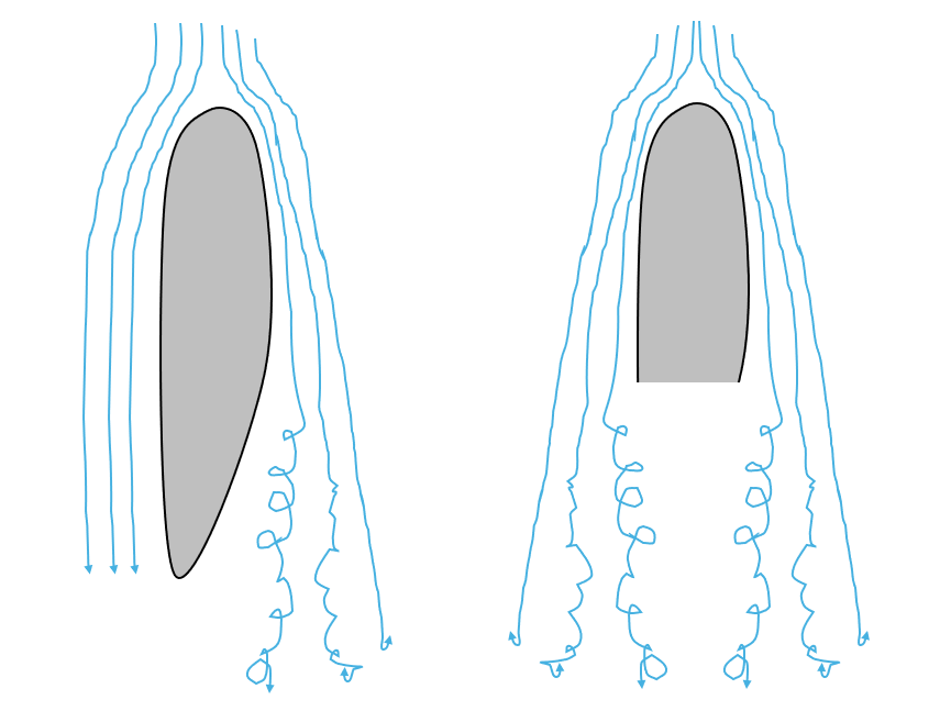
Make the airflow break away in a predictable way. Chop the rear bit of the wing or fuselage off and the airflow will separate predictable way leading to consistent lateral forces on the tail and the aircraft will be more stable in yaw.
The problem? It’s more drag! The H145 is undoubtedly slower than many similar sized helicopters and this could be one source of the problem.
Double Gurney Flap?
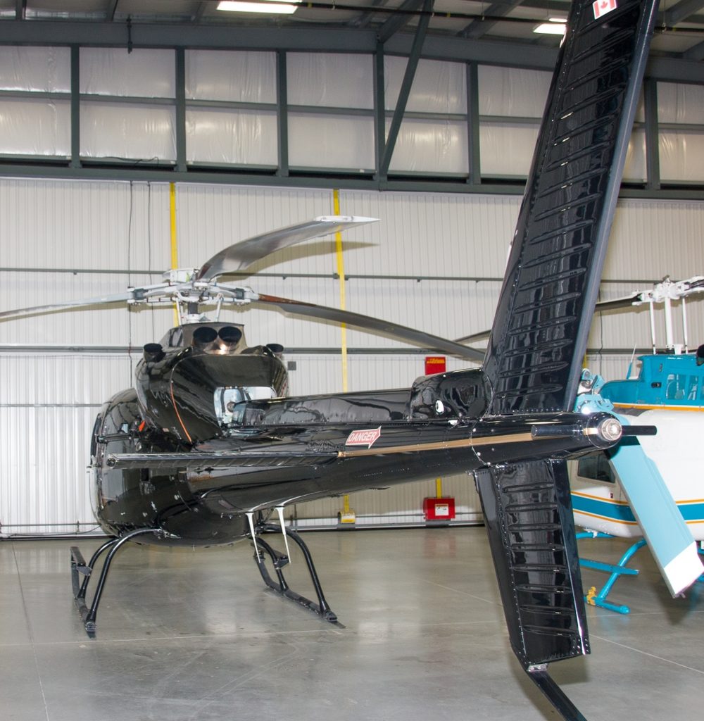
As we mentioned earlier, there is another use of Gurney Flaps. On some helicopters, such as the AS355, the vertical fin has Gurney Flaps on both sides the vertical fin. This is installed for similar reasons to the blunt rear end on the H145 tail. It induces a predictable airflow separation at the rear edge of the tail fin, reducing unpredictable yawing moments and a control headache for the pilot.
Now for the last tweak – what is that ridge on the front of the tail fin?
H145 Vertical Stabiliser – Stall strip
As we saw earlier, someone has stuck a triangular ridge on the H145. This feature is not present on the H135 so something peculiar must be going on.
There are a few things to note with respect to this strip:
- It is only forward of the fenestron, not all the way to the top of the fin
- It is mounted slightly off centre to the left when looking backwards down the tailboom
- It rising gradually on the left but drops sharply on the right when looking back along the tail boom
Is there anything else in aviation that looks similar?
Stall strips
Take a look at the front of the wing near the root on many aeroplanes and you will see something very similar. A small triangle section wedge is placed on the leading edge of the wing.
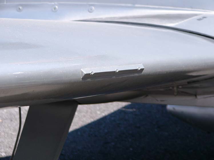
The purpose of the strip in aeroplanes is to initiate a stall of that part of the wing before the rest of the wing. This produces the signs of a stall before the whole wing stalls. The turbulence from the detached airflow goes over the tailplane and induces buffet which the pilot can feel. As the wing with ailerons has not stalled yet, the pilot maintains control of the aeroplane to exit the stall.
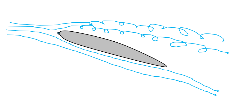
Of note, the stall strip doesn’t cause significant drag or handling issues when the wing is in normal angle of attack range.
Stall strip in a helicopter
Ok, that makes sense for an aeroplane but why are we trying to stall our fin? Wouldn’t that lead to a sudden yawing motion in our helicopter?
Let’s look at when that stall strip would come into effect. What condition are we trying to overcome? That wide fat fairing around the fenestron is the culprit. Due to the size of the fan and the depth needed for the duct, the fin is very wide at the front ahead of the fenestron.
In forward flight, there isn’t a huge problem as the fin does most of the work in providing directional stability so the problem is in the low speed envelope.
At low speed the fenestron is doing all the work of providing directional stability and control. Any changes in the airflow through that fenestron will induce changes in thrust leading to heading control problems for the pilot.
When are we going to find changes in the airflow? What about turbulent air from the fin? When would that occur?
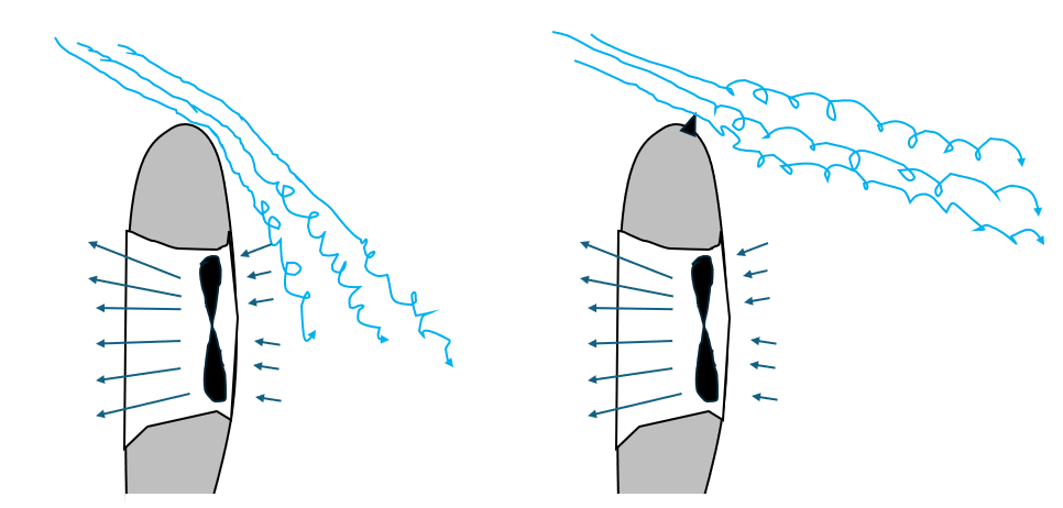
The “intake” side of the fenestron is the right side. Any “bad” air here will lead to thrust variations. The stall strip trips the airflow in left sidewards flight so it ends up clear of the fenestron intake, allowing for smoother control in this flight regime.
During flight test, the flight test team likely found a speed regime in left low speed flight where there were sudden yaw thrust variations making control difficult.
But perhaps it was not a perfect fix. The following note can be found in the performance section of the H145 Flight Manual:
Wind (>25 kt) from the left (270 degrees +-10 degrees, area A) may require increased control activity and/or large pedal inputs to maintain aircraft heading.
Tweak summary
In summary, the H145 has quite a few aerodynamic tweaks around its tail, to prevent or overcome some handling issues found during its development program:
- Gurney Flaps – both in the normal and unconventional direction
- A blunt rear end
- A stall strip ahead of the fenestron.
The H145 is undoubtedly slower than some of its peers and perhaps these tweaks contribute to that, but the resulting handling and ride (at least on the D3 with the new blades) is smooth and predictable.
Now check out our other articles.
- H145 Aerodynamic Tweaks Explained: Gurney Flaps and Tail Design
- FSTD Capability Signatures (FCS) – A hidden threat for training?

- Preparing for complete loss of engine power in helicopters
- Lessons in how to manage a helicopter engine malfunction
- Light twin helicopter AFCS – Have Airbus won the race?
- Maintenance by pilots – can the training be improved by sharing?
- Flight simulation revolution – A new method for matching training need to simulator capability
- Helicopter Single Engine IFR – New horizons
- Making the grade – understanding climb gradients in the go around
- Unfair Skies: Restrictive helicopter instructor rules and how to fix them
- How to create an instrument rating instructor (IRI) – A helicopter anomaly
- The evolution of Category A Helipad procedures – A strong foundation for VTOL to learn from?
- Strips vs dials – Which is better?
- Under the weather – are UK HEMS weather rules broken?
- Mastery of the GTN 750 – Ten things you should know

Leave a Reply