
Automated take offs are now a reality on commercially available helicopters including the H145, H160 and H175 with the latest Helionix software. Given pilots have successfully been taking off without such automation for years are these new systems unnecessary complexity or should they be standard fit for future helicopters?
In this article we look at the automated take off features introduced on the H145 at Helionix software version 10 and look at how they might be used during operational flying.
Let’s get stuck in.
Contents
- Helionix Basics
- What has been automated?
- How to do an automated take off – RTOL/ERTOL
- Automated take off – VTOL
- What it can do
- What it cannot do
- Comparison to cars
- Conclusion
- Thoughts for the future
Helionix Basics
Before we can understand what new capabilities are introduced, we first need to establish what Helionix is and how it forms the basis for what is to follow.
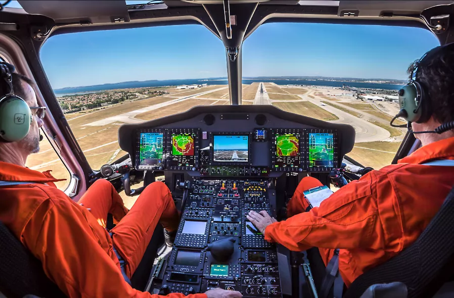
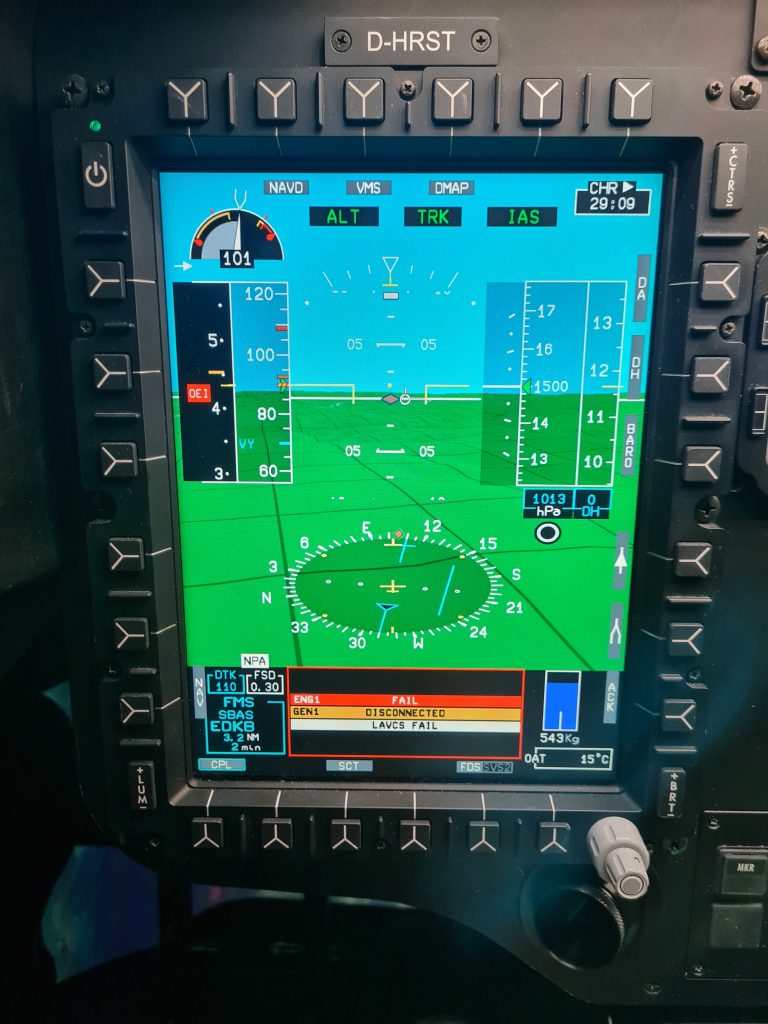
Helionix is an Airbus-developed integrated avionic system first introduced on the EC145 T2 (now H145 D2) back in 2016. It brought together many disparate flight display, automatic flight control, aircraft and engine health monitoring and ancillary systems into one common display and control architecture. It was later integrated into H135 and was the core system from day one for H160 and H175.
Core Helionix features
So what does Helionix bring that improves upon the previous cockpit designs (specifically the earlier EC145 C2 FCDS/CPDS cockpit).
Common architecture
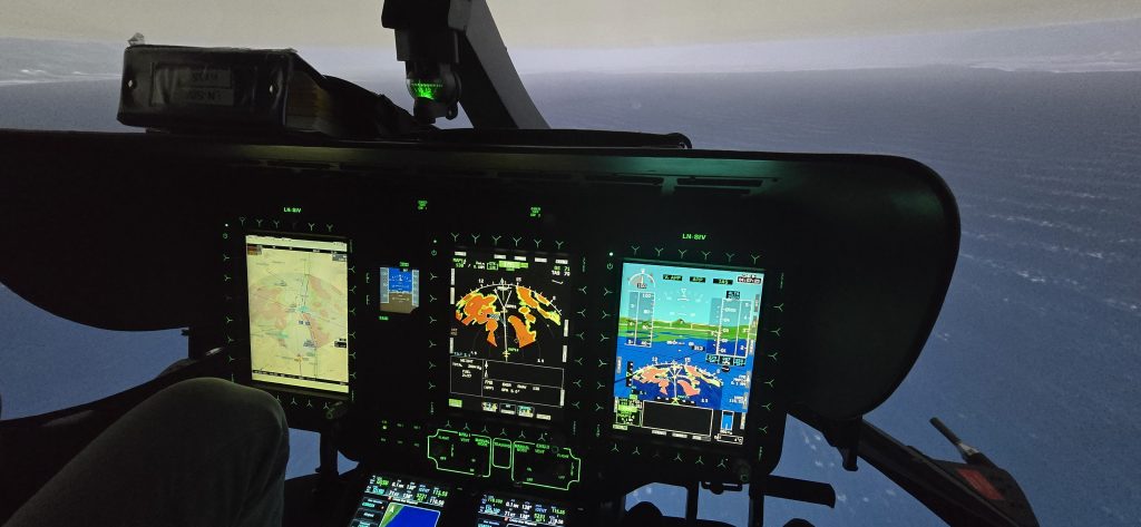
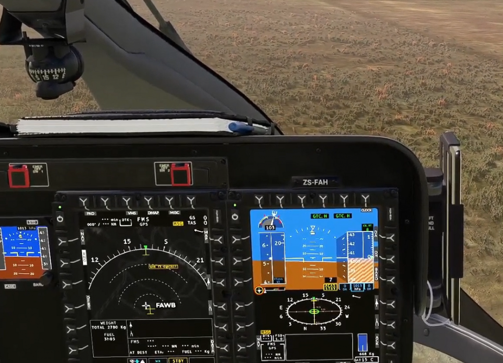
The main feature of Helionix is that it is a common platform which can be adapted for a variety of helicopters. The system information is displayed on Multi Function Displays (MFD). However, the number of screens is adapted to the helicopter and the role. The H135 can have just two screens, giving room on the left for a mission equipment display or just space for the technical crew member. This is the configuration used for the new UK NPAS police aircraft.
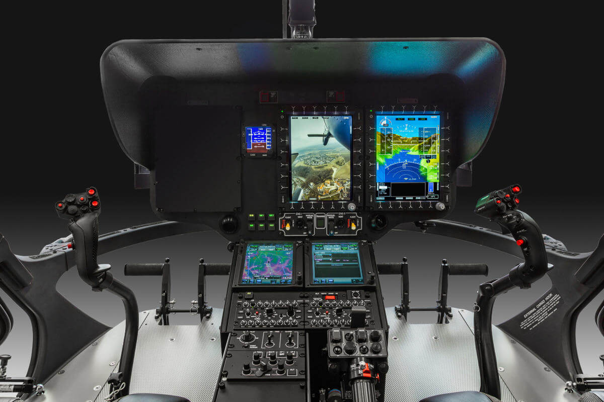
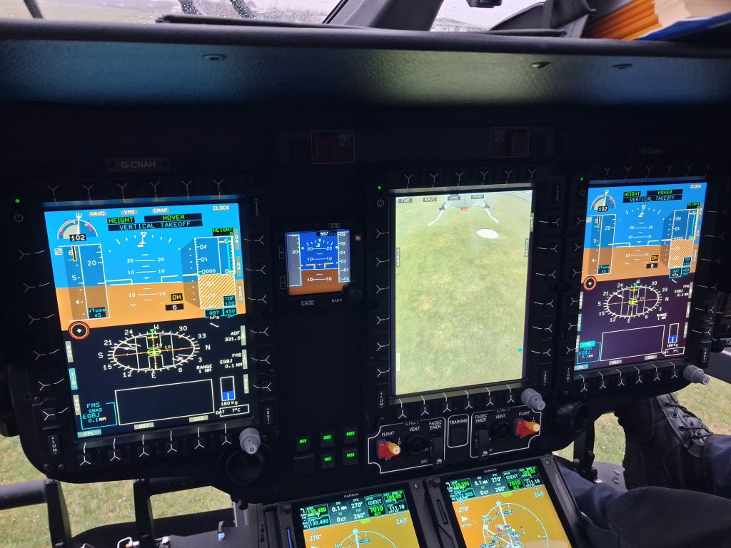
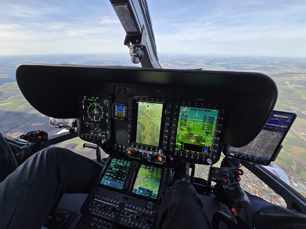
The system can be scaled up to a four screen cockpit with the increased cockpit real-estate allowing for an external role equipment screen in the centre.
The core Helionix system can plug into a variety of other avionics whilst delivering a consistent display of the information. Note the H135 image above shows twin GTN 750 navigation units whereas the H175 has twin FMS units.
Consistent logic
As well as having a consistent core architecture, Helionix has a consistency of display and interaction both between aircraft types and between functions on each aircraft. A pilot who can fly one Helionix type is usually given credit for this when converting to another type (although currently not when converting from H135 to H145 due to a somewhat underdeveloped OSD-FCD by Airbus).
Functional interaction on the system is consistent. Want to adjust a parameter on the display? Select the appropriate Line Select Key (LSK) to select the appropriate function think twist the lower right knob to adjust it and you’re done. This compares favourably to the Bell Badger Pro+ displays on Bell 429/412 where an extra button press on the LSK is needed to accept the change – it is amazing how one extra button press for every interaction soon adds up.
Built in 4 axis AFCS with sophisticated upper modes
The Automatic Flight Control System (AFCS) which is hosted on Helionix is an incremental upgrade of Airbus autopilots going back to much earlier aircraft. Pilot’s with experience of earlier Airbus types like the EC135, EC225 or AS332 will recognise the lineage.
Advanced modes
Even the smallest Helionix machine, the H135 comes with some very advanced modes such as hover and flight path angle modes. These are a core foundation of how the take offs are automated (see later). Native hover modes are an omission on many light twin helicopters limiting their ability to catch up to Helionix.
4th axis
The other aspect of the AFCS which essential for automation is the 4th axis. Collective modes form an integral part of the automated take offs and significantly reduce pilot workload – see our article on the pitfalls of just having a 3-axis AFCS. IFR operations with Helionix 4-axis AFCS engaged can almost be boring the aircraft is so good at reducing the pilot’s workload. Almost.
With full control of the aircraft possible through the AFCS other refinements are possible. The “Recovery Function” which engages speed, altitude and heading control is a useful part of an upset recovery.
GNSS aiding
The AFCS also has GNSS-aided modes to follow a track or an angle of descent. Both incredibly useful in flying with any wind. Some other manufacturer’s attempts at a track mode are politely, crude bodges of the system by comparison.
The linking of nearly every AFCS mode datum to the cyclic and collective beeper trims also dramatically reduces the need for the handling pilot to take their hands off the controls (Bell’s system does not allow this for heading for example – you have to use the heading knob on the centre console).
To summarise, the Helionix AFCS is very good and we have barely scratched the surface.
Flexibility and capability
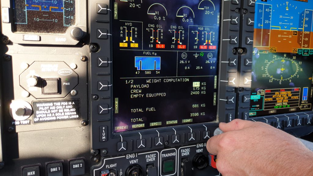
Helionix allows a wide variety of display configurations to suit the role and situation. Due to the internal monitoring system of Helionix, temperatures and pressures for the various systems do not need to be constantly monitored by the crew, freeing up a screen for other uses.
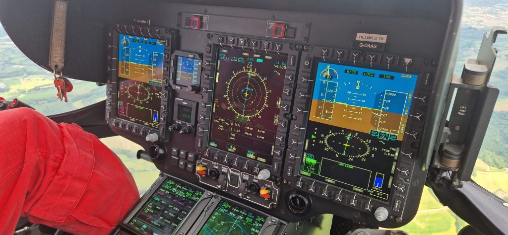
The Helionix system also includes an HTAWS system which means that a Synthetic Visual System (SVS) can be displayed as an alternate to the normal Flight Navigation display. This further frees up other screens to be used for other sensors or data without having to dedicate cockpit real estate to terrain monitoring. As we discussed in our article about Norwegian Air Ambulance, the Helionix system can be set up to give a single pilot unprecedented situational awareness under IFR.
Precursor features necessary for automated take offs
Given the Helionix infrastructure, why weren’t automated take offs available from day one on the EC145 T2? To get to the current state of the art, 2 key developments had to occur first in Helionix, building on its early foundations:
- Hover mode with multi-sensor height control
- Control of collective to preserve NR when OEI
Hover mode with multi-sensor height control
The Helionix AFCS suite has included a hover mode (Ground Trajectory Command – Hover (GTC-H)) from the beginning but integrating a vertical mode is a recent innovation. In the early days you could engage the hover mode, then select a suitable vertical mode to go with it such as CRHT (Cruise height – rad alt hold) or ALT (Barometric altitude hold).
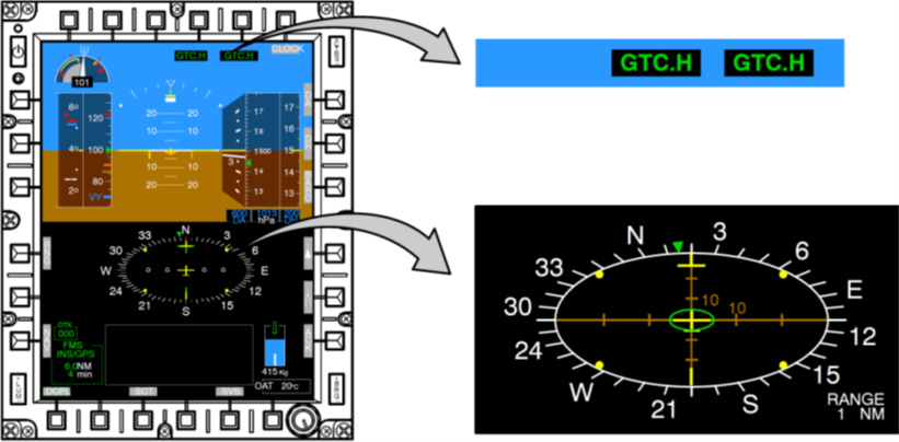
In the latest version, now called HOVER, a composite vertical mode is introduced which uses a mix of barometric altitude, radar altitude and inertial information to give a smooth steady hover in all axes. The automation can build on this composite vertical control to smoothly control the helicopter precisely in close proximity to the ground and while transitioning over wildly different surfaces.
This latter point is particularly relevant as during automated take offs from elevated pads, the aircraft transitions from a free air hover to being over the deck. Control of vertical position using just radar altitude would be a spectacular failure and using barometric altitude could be influenced by suddenly entering a ground cushion.
Control of collective to preserve NR when OEI
In the original Helionix AFCS modes, collective control when OEI (One Engine Inoperative) came with some severe health warnings. For example, in the Go Around (GA) mode notes in the appropriate Flight Operations Briefing Note (FOBN 12-22) it states:
In OEI, the pilot must actively control power and NR by acting
on the collective.
− At the OEI 30” or 2’ rating, the autopilot will not maintain
the rotor speed. The NR could droop dangerously.
− At the OEI Continuous rating, the autopilot will not prevent
the use of OEI 30” or 2’ power.
This is clearly not a great basis for an automated take off. Pilot’s would have to override the system which could lead to significant deviations.
Airbus have refined the vertical modes through incremental progression and now Go Around does an excellent job of selecting the appropriate power setting (2 min or 30 sec) whilst preserving the rotor speed at a safe level. The Go Around mode also now automatically engages a lateral mode (eg TRK or HDG) and can also be used from just 4 ft above ground.
What has been automated?
Now we have the basics developed, what have Airbus actually automated for us? The focus is on take offs where the pilot’s view is restricted – the rearwards and vertical take off profiles. For now, the clear area departure has not been left out.
RTOL and ERTOL
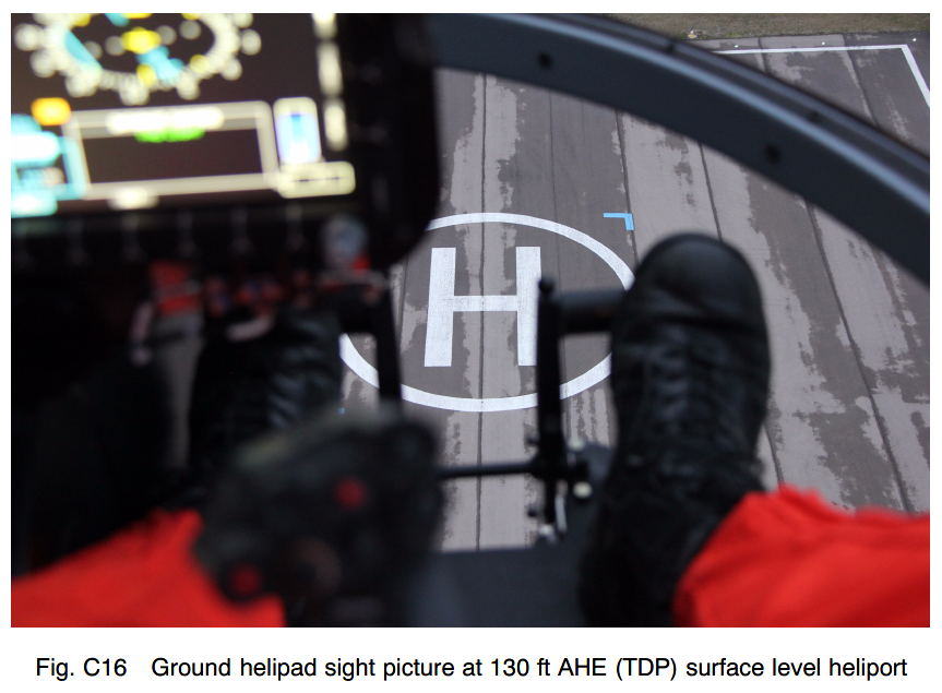
On the H145, the Rearwards Take off and Landing (RTOL) and Extended RTOL (ERTOL) are types of Category A take off profile which aim to keep the landing site in between the pilots feet in the chin window during the departure and reject. The profile is relatively steep compared to many light twin helicopters; see the diagram below – see our article on Category A back up profiles for a full comparison.
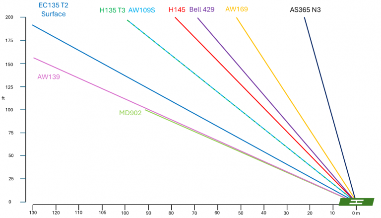
The major capability difference between the RTOL and ERTOL is the maximum obstacle it is possible to transition over – 80 ft for the RTOL and 270 ft for the ERTOL. The take off profile is normally flown by the pilot focussing on the pad between their feet and controlling the aircraft manually in all axes to achieve the climb. The view of the pad is not great.
In the event of a rejected take off before TDP, a short duration nodding manoeuvre is conducted to arrest the climb before the pilot again focusses between their feet for the descent. In the event of reaching TDP and then detecting an engine failure, the pilot flies a forward transition through specific speed profiles using the 2min and 30 sec power on the remaining engine to achieve a safe climb. Go around mode can be used to assist but it may not follow the Category A profile
Vertical – VTOL
In the vertical departure, the GTC.H hover mode is used to establish a steady hover over the designated launch point. The pilot then uses collective to initiate a climb to TDP. Longitudinal and lateral position are maintained by the hover mode.
If a rejected take off is flown before TDP, the hover mode remains engaged and the pilot controls rate of descent/rotor droop/power management with collective. If an engine failure occurs after TDP, the pilot again has to initiate a forward transition, managing speed and power to follow the Category A profile.
So how has Airbus automated the process?
How to do an automated take off – RTOL/ERTOL
Let’s run through the procedure for an automated take off after a normal startup to highlight how it works. We will focus on the RTOL for the first one:
- Setup AFCS upper modes for initial cruise phase (eg speed and ALT.A)
- Display hover view on Flight Navigation Display (FND) (in place of HSI)
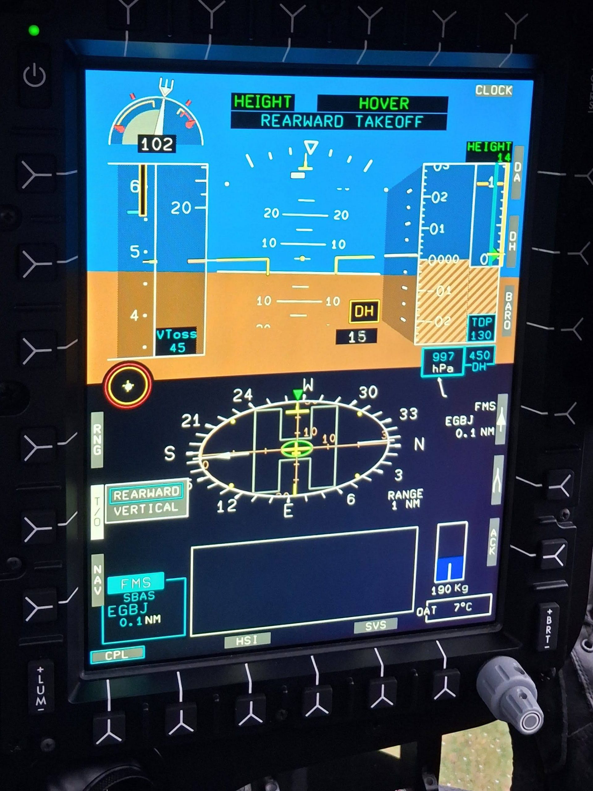
- Press the soft key with label T/O on the FND (can also be done once in the hover as shown below)
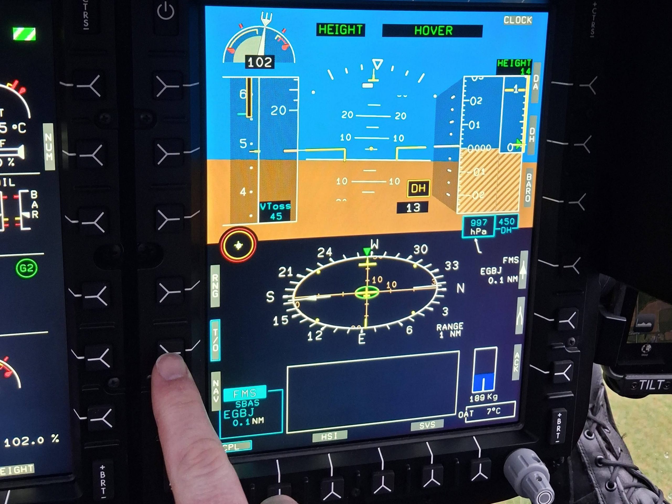
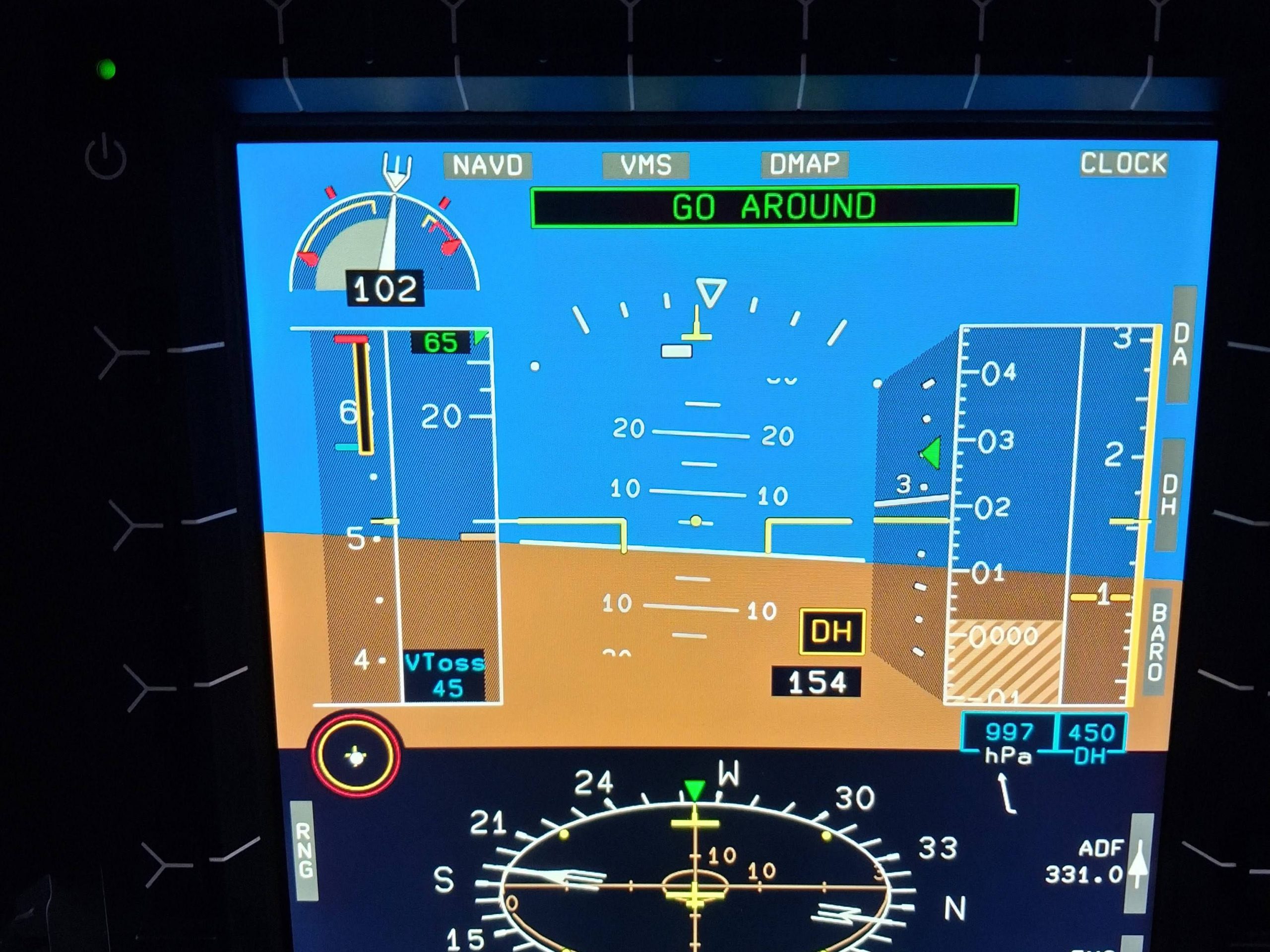
- Now choose the type of departure (remember the consistent Helionix method described earlier – softkey then rotate knob). Note the default TDP has popped up on the right above the DH bug setting.
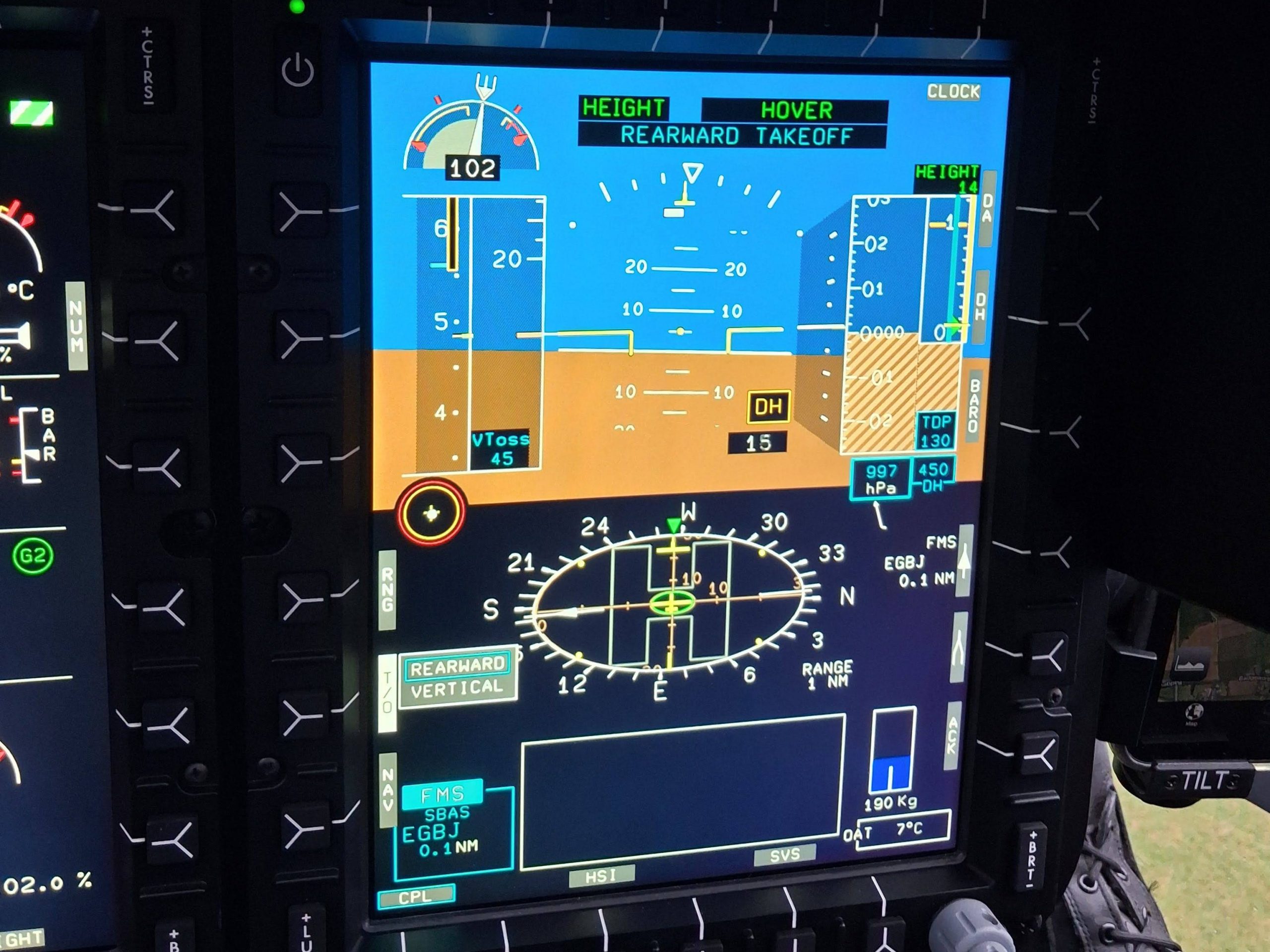
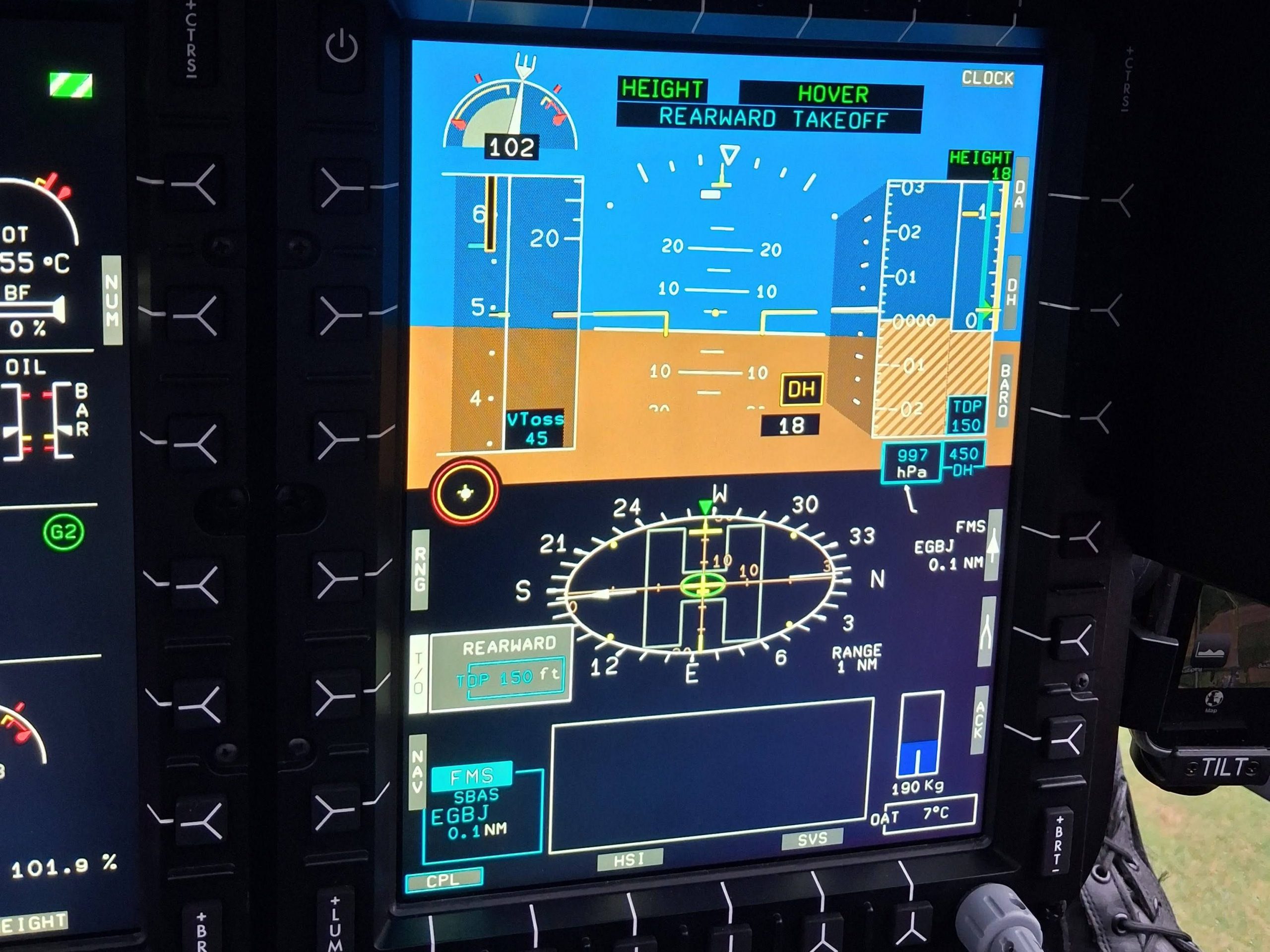
- Adjust TDP to suit obstacles in departure path. In this case 150 ft TDP is required to account for a 20ft obstacle in the departure path
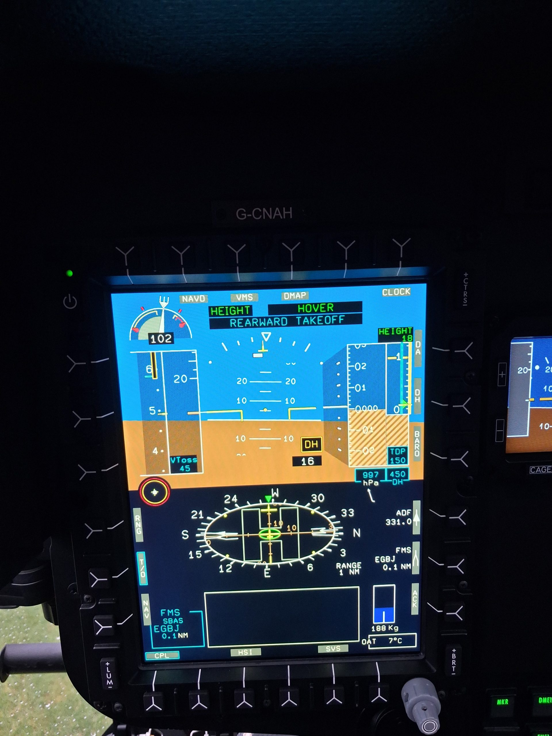
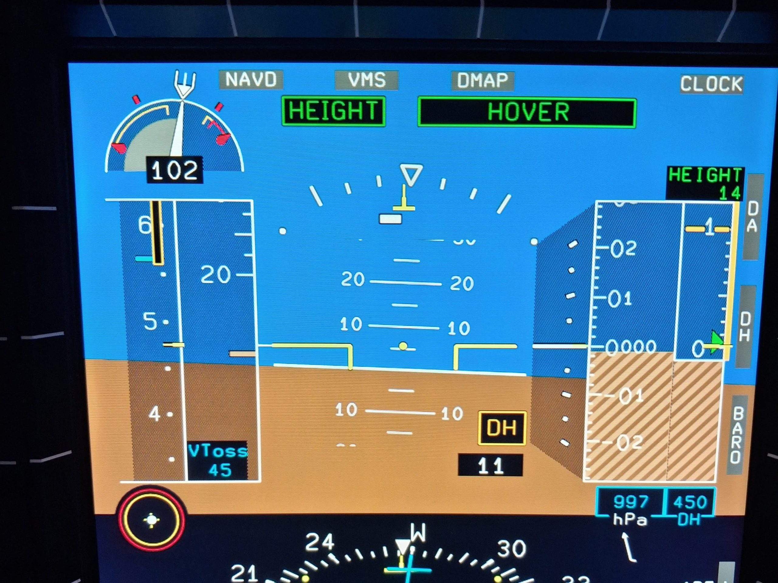
- Get airborne (if not already) and engage HEIGHT/HOVER mode (2 taps on the relevant cyclic button). Adjust to 10 ft and adjust the heading to align with the departure path (squeeze of the pedals or beep the yaw)
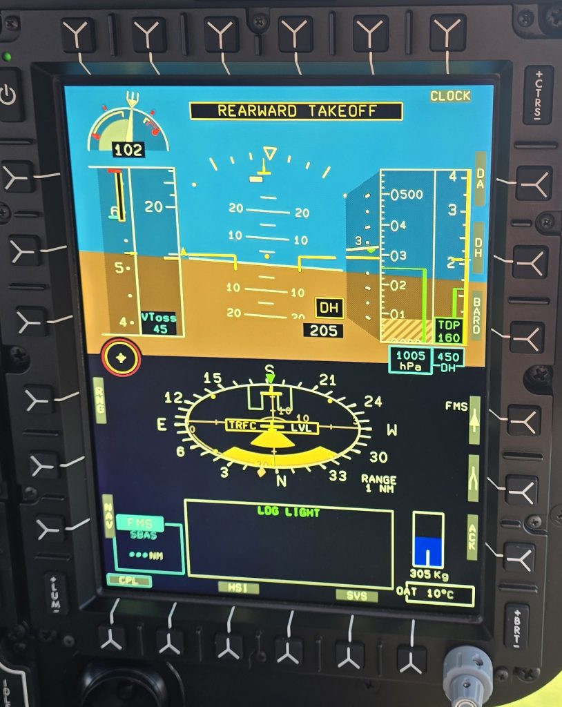
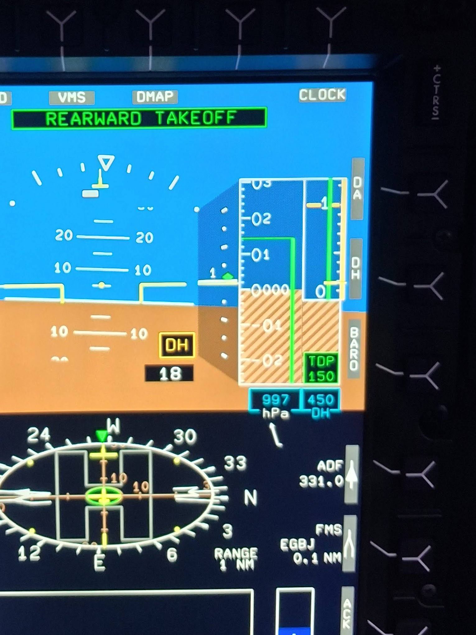
- Double tap the GA button on the collective. REARWARD TAKEOFF displayed and sequence starts. The target TDP is now shown in the barometric altitude display and radar altitude display (remember the composite height mode from earlier?)
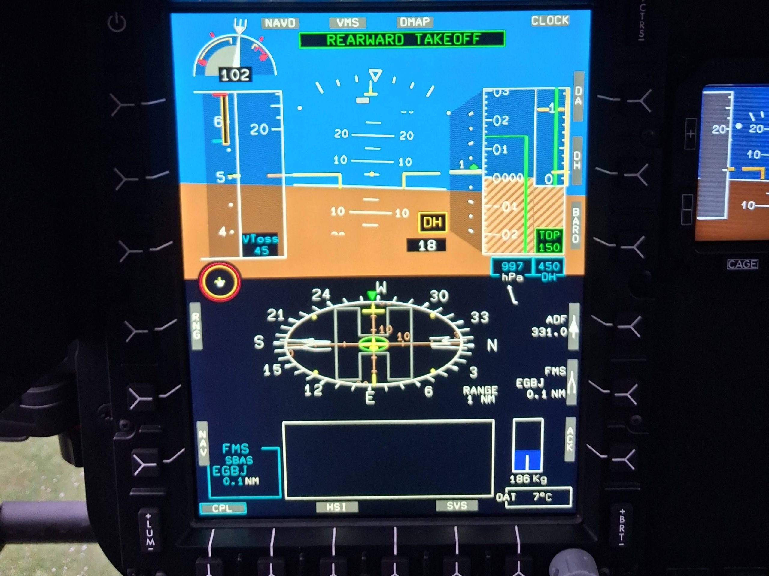
- The The take off point is memorised by the system and the AFCS guides the aircraft into a textbook vertical rearwards climb towards TDP.
- On reaching TDP, the pilot pressing GA once more and the aircraft accelerates away in accordance with the published profile. The pilot cannot select GA earlier than TDP (it just does not work)
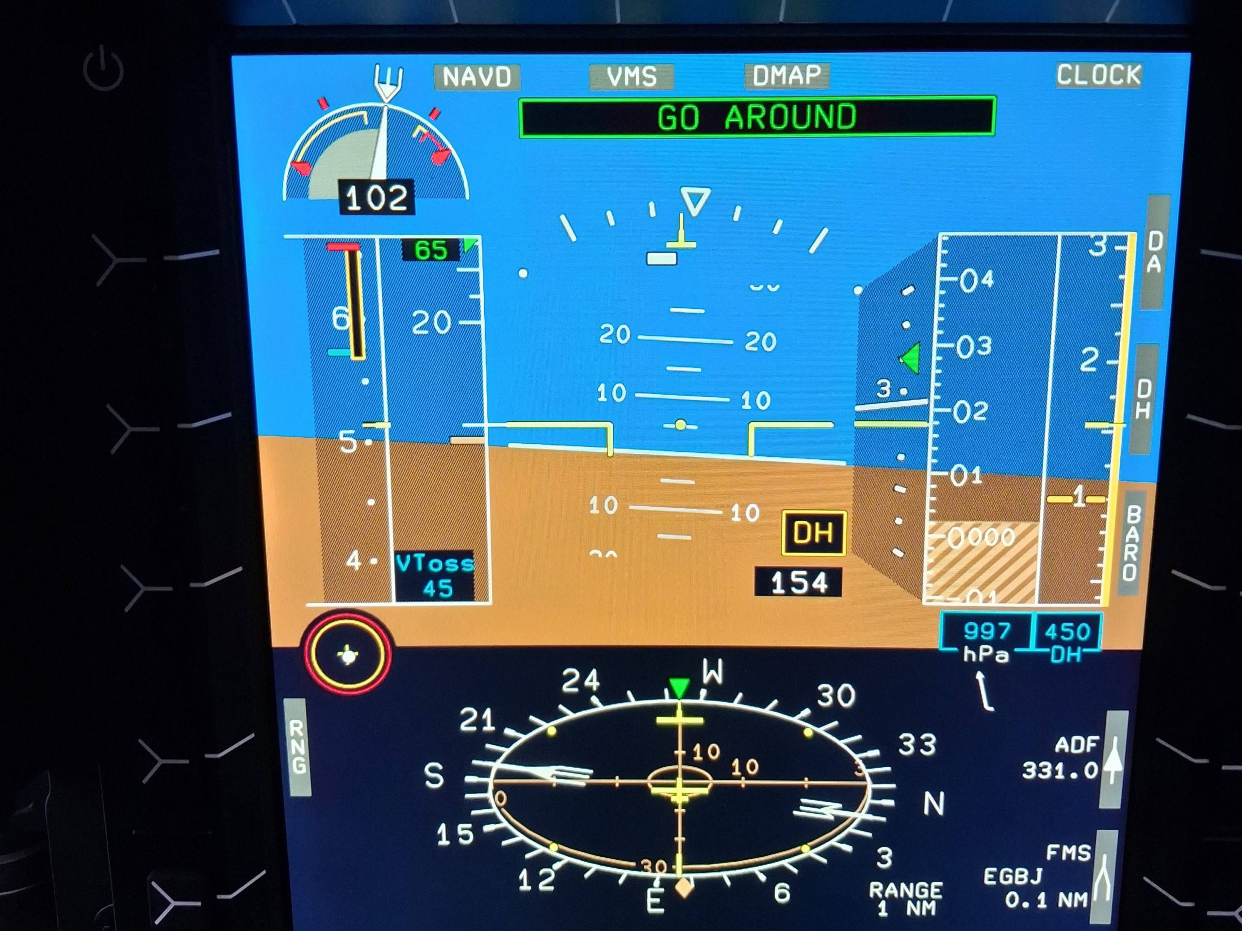
- As speed passes 30 kts, the pilot can couple up to a navigation mode if desired. The aircraft will level at the selected ALT.A altitude at the pre-selected speed. Voila!
Engine failure after TDP
OK that’s fancy, but what if an engine quits? Let’s look at an engine failure post TDP first.
- Engine fails after TDP. Aircraft automatically engages CONTINUED TAKE OFF and flies the aircraft exactly in accordance with the published profile. It will use the 30 second power rating initially. The pilot selects the 2 min rating using a button on the collective on reaching VTOSS and a positive rate of climb. NR is automatically maintained throughout
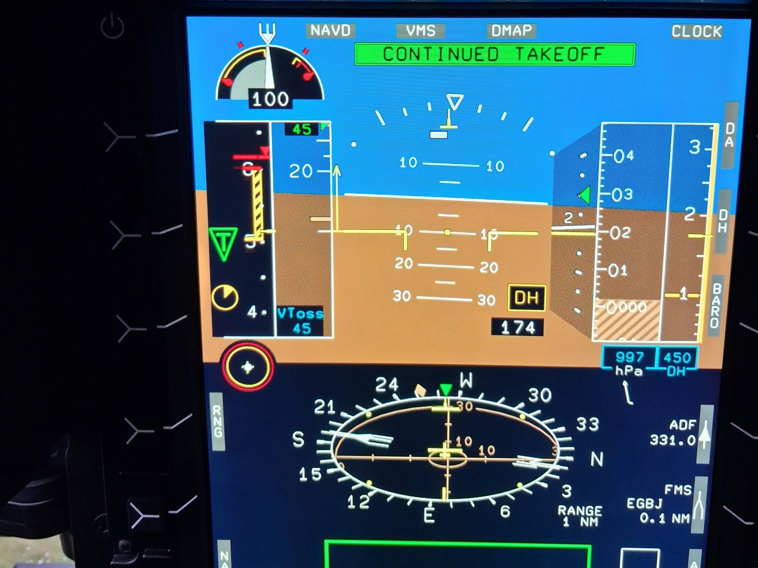
- On running out of the 2 min rating, the AFCS automatically selects a rate of climb of 150 ft per min (textbook numbers) but the pilot can adjust up to Maximum Continuous Power (MCP) if desired. The climb continues as planned.
Engine failure before TDP
OK, really fancy but that’s just the Go Around mode. What about if the engine quits before TDP. Well this is where things get fun!
- If an engine fails before TDP, the AFCS automatically engages REJECTED mode and manages power to initiate a descent whilst using the available power and maintaining rotor speed
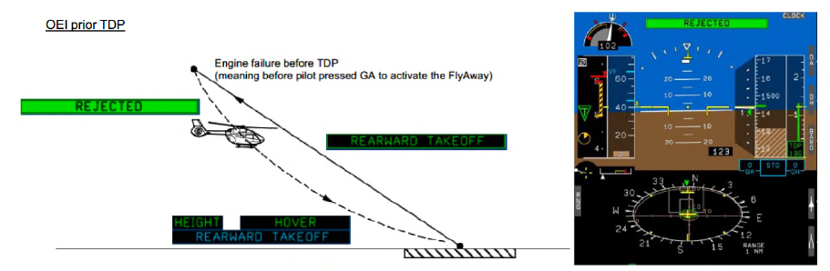
Well where’s the fun in this? The fun part is the AFCS knows the aircraft better than you do. The selected rate of descent used by the AFCS can be described as “sporty”. The AFCS has baked-in protection from the vortex ring state in this flight condition but it certainly seems to be trying to throw you at the ground.
The pilot suddenly has a role at this point. At 15 ft above ground (visually judged!) the pilot has to intervene and execute the landing. Completing a landing is a highly nuanced manoeuvre which is (currently) beyond the installed AFCS’s capability. This almost encourages a dangerous game of chicken where the pilot wants to see how late they can safely come in on the controls, but fortunately training takes over. The landing is actually not difficult as the aircraft is exactly where it started.
Automated take off – VTOL
The process for a vertical take off (VTOL) is nearly identical except the forward looking camera under the tail is shown on the centre MFD (if the camera is fitted).
What it can do
So what is within the scope of the automated take off? What else is part of the package?
Variable TDP
To account for obstacles in the take off path, the TDP of both RTOL and vertical take off modes can be adjusted appropriately (max 400 ft for RTOL/ERTOL or 210 ft for VTOL).
Night departures
The AFCS does not use any visual systems so is able to complete the departure by night just as well as by day. Having an automated vertical take off or even a native hover mode in the AFCS would have gone a long way in preventing several accidents were a helicopter drifted into obstacles during departure. For example on 1 November 2022, an AW109 drifted into trees during a night take off from a field landing site at night; a vertical hover-mode assisted take off may have helped – see the AAIB report.

HEMS departures
The VTOL departure is particularly suited to HEMS sites. One hitch with using the automated take off is that an accurate VTOL is needed and assessment of obstacles can be a bit of guess work. The pilot can always revert to manual flight
Cope with variation
The automated take off must be monitored. Helpfully, the AFCS also monitors itself. If a deviation it can cope with is detected it displays an amber indication. If things start to go off the rails, a red indication is shown so the pilot knows to intervene.
No requirement for a barometric altitude correct on elevated pads
Due to the AFCS putting the TDP for automated take offs in both the radar altimeter and barometric altitude channels, no increment on top of TDP is required at elevated pads. For non-automated take offs from elevated pads using barometric altitude as a reference, the increment of 70 ft on top of TDP is needed to cope with barometric altitude errors. That’s 70 ft of extra climbing flight exposing the crew to a risky flight regime – this extra increment is not needed for the automated take off.
What it cannot do
The automated take off sounds perfect. It does however had limitations. It cannot:
Seeing ahead or sideways
The AFCS cannot see the actual environment around the helicopter. If something moves it has no means to detect this or to realise if a deviation from the flight path is getting the helicopter uncomfortably close to an object. The pilot must monitor the situation and surroundings.
Factoring obstacles
The AFCS does not know what the obstacle environment is around the helipad. The pilots must make the appropriate calculations to gain an accurate TDP to enter into the system. This needs good data and a through understanding of performance and some really good software tools as it gets complex very quickly.

Clear area transitions
Currently the automated take off is restricted to the RTOL, ERTOL and VTOL take off profiles. A clear area profile may follow in future should demand be sufficient
Landings
An automated touch down is currently not available. The last 15ft of the reject needs pilot intervention – we are not out of job yet. The nuances of getting a skidded helicopter safely in contact with the ground is beyond the AFCS’s capabilities – for now.
Approaches
Making an approach into a landing site is an entirely different ball game to a take off from a site you are already in. There needs to be consideration of marking the desired landing site accurately in the system and factoring obstacles.
Comparison to cars
Before making a judgement, it is worth a quick comparison to some recent innovations on cars. The technology for parking has come along in leaps and bounds in recent years. Take the process of parking in a space alongside a road. Cars can now come with a fully automated car mode that does the steering and accelerated to get into tight slots.
As part of the system, a 360 camera was installed. Great fun to watch the car drive into the space on the overhead view. Except it sometimes got it wrong and the driver needed to intervene. The driver found the 360 camera was sufficient to achieve the desired parking using their own inputs with fewer errors. The automated mode never got used.

The next time the driver bought the same model of car, they just got the 360 camera option and left out the automated mode. The next time around, the automated mode had been deleted from the options list due to lack of interest.
Is the helicopter automated take off going to suffer the same fate? Is the automated take off a pointless feature or a new essential like the 360 camera on a car?
Conclusion
The automated take offs implemented on H145 are remarkably simple to use and reliably produce consistent results both under normal conditions and engine failure cases. Pilots who have used the new comments that it is so simple to select and engage the mode that “Why not use it?” is the response. This is a common refrain about many of the AFCS features on Helionix – they are easy to use and produce consistent results so why not use them?
The automated take offs are not appropriate in every circumstance of course. A complex HEMS departure requiring a downwind take off or significant yawing changes during departure might be out of scope. Offshore and runway departures are also not yet implemented so the humble pilot lives to fly another day.
However, the conclusion has to be that the automated take off should be part of helicopter AFCS going forwards. They mitigate many risks of operating in complex obstacle environments by dramatically reducing pilot workload.
Once you have tried them, you will wondering why other AFCS are so far behind.
Thoughts for the future
One key community that needs to look at these developments is the eVTOL world. Although their certification is still not certain and many have fallen on the path, if they do come to market they need to be exhibiting automation on a level or better than currently available on Helionix.
A manually flown shallow back up departure is just not going to compete when an in service mature helicopter has such advanced capability. We will investigate what else eVTOL can learn from the helicopter world in a future article.
Why not take a look at some of our other articles?
- Automated take offs – Pointless or are they the new standard?
- Keeping up with the Norwegians – Six amazing innovations for UK HEMS
- LNAV/VNAV (SBAS) – Are they approved for use in the UK?
- Helicopter 2D IFR approaches – Is CDFA the best choice?
- Understanding Helicopter Flight Manuals – Everything you need to operate safely

- Post Maintenance Flight Tests – How to avoid fatal traps

- First Limit Indicators in Helicopters – Deadly mistakes to avoid
- Bad Vibes – How to report vibrations on helicopters
- Autopilots, cross-checks and low G in helicopter unusual attitude recovery
- Expert site surveys – Improving the assessment of onshore landing areas
- Lights, helipad, action! The problem with new helicopter pad lights
- Helicopter on Fire – Could accident investigators have learned more?
Leave a Reply