

First Limit Indicators (FLI) or Power Situation Indicators (PSI) are displays in glass-cockpit helicopters which bring together all the engine power parameters into one simple display. These displays can dramatically lower the workload of a pilot, giving a single visual indication of the power state of the aircraft relative to its limits.
FLI and PSI can also give a really clear indication of which engine is causing a problem in the event of an emergency but they can also mis-lead the crew into putting the aircraft in a deadly undesirable state. In this article we look at the technology that is out there and identify some pitfalls to avoid. We also look at some past incidents where mis-interpreting the display lead to fatal crashes. At the end we will offer up a practical way to manage engine emergencies on an FLI/PSI equipped helicopter.
This article is focussed on multi-engine helicopters. It may be useful for some single engine helicopters with an FLI/PSI but that is not the aim.
Contents
Evolution of the FLI on Helicopters
Engine Parameters
So why did First Limit Indicators (FLI) come into use? On multi-engine helicopters, there are general a set of at least 3 indications of interest for determining the power and loading of each engine:
- Torque
- Engine speed
- Engine temperature
These terms are given different names depending on the aircraft and engine manufacturer and learning these are part of the joy that is a type rating. So for and Airbus EC135 it is: Torque, N1 and Turbine Outlet Temperature (TRQ, N1, TOT). For a Bell 429 it is : Torque, Gas Generator Speed and Measured Gas Temperature (Q, NG and MGT). For AW139 its torque, inter-turbine temperature and gas generator speed (TQ, ITT and NG). Despite them being measured in different ways (particularly the temperature), broadly they are equivalent terms.
In addition we also want to comprehend the energy state of the drive system and rotor, so we need 2 more parameters
- Drivetrain speed
- Rotor speed
These are normally known as N2 or NP for drivetrain speed and rotor speed as NR but they are typically always shown on dedicated displays so we are not going to focus on them for now.
We are also not going to look at the FLI as found on the Helionix Airbus helicopters to begin with – we will come back to that!
Analogue Displays
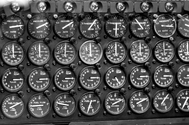
So on a twin engine aircraft we have 3 gauges per engine – how are we going to display them? In the early days of helicopters, dial-type “steam” gauges were the norm. So we have 6 dials to arrange. This is not a lot compare to some fixed wing types like the mighty B52.
Torque as primary instrument
The most important gauge in a temperate, sea-level environment is torque. This gives a direct indication of power from an engine and at sea level in a temperate environment is the first parameter that will reach a limit. Typically, both engines are shown on the same torque gauge, making comparing the load on the two engines easy – in an emergency the split on the torque needles is a great indication that something is wrong. Hence, a typical verbal call by a pilot of these machines would be a “Torque split!” in the event of an engine failure. We will come back to that.
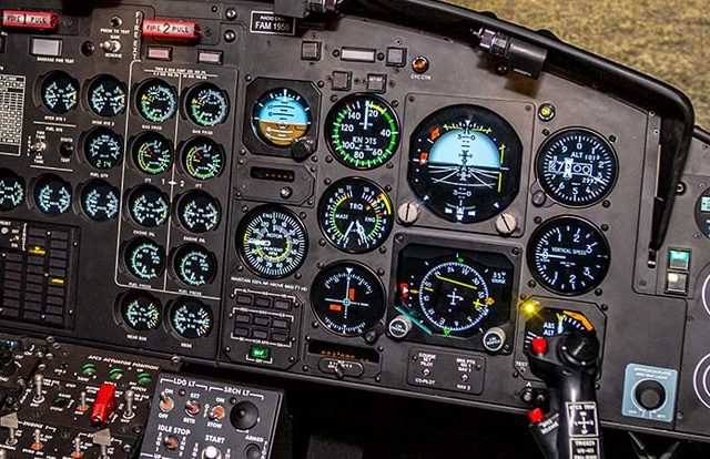
Given the dominance of the torque gauge for managing power, it is often located close to the flight instruments but away from the rest of the engine displays. See the Bell 412 cockpit below as an example.
There are of course other ways to do it. On the SA330 for example, there was no torque gauge but there was a collective pitch gauge. But for the sake of this discussion it does not actually make much difference – there is some primary power gauge.
However, torque is not always the limiting parameter. In hot, desert environments, engine temperature can be limiting. When very high and/or very cold, engine speed can become limiting as the engine struggles. Now the pilot has to look at some gauges that are much smaller and further from the pilot’s natural forward view (see Bell 412 cockpit above). Not ideal; we can do better.
Electronic Displays without FLI
Basic digitisation
The next step in engine instrument design was to digitise the information and display in a clever fashion on an electronic display. The AW109E is a good example of this. In this case with its PW206 engine, it’s TRQ, TOT and N1 for the key parameters. The parameters are in the this order away from the pilot as they are in the order of being most likely to be limiting.
This is a good first start, but a lot of display real estate is dedicated to parameters which are not usually limiting in temperate environments. Again we can do better.
The Hockey Stick
The next step is to combine the information on one gauge. This makes efficient use of cockpit real estate. In the example of a Merlin below, the triple torque gauge is overlaid with other parameters when they are more limiting through a yellow hockey stick which extends down to show the new limit. The torque gauge is a fixed strip with a moving indication. Fairly easy to interpret where you are in the power range. More detailed information was presented in a similar way to the AW109 on a central screen.

However, Airbus and others thought they could go further by going back to a dial-type display and simplifying by removing the units and types of input (TQ, TOT, N1) all together. So was created the FLI!
First Limit Indicators (FLI)
The FLI design goal was to present the power output and limitations of the engines in a consistent, easy to read format. No matter where the helicopter was, no matter the environment, the pilot had a simple goal – kept the needle in the right part of the gauge. Clever electronic wizardry normalised all of the parameters so that the red line is the same place on the gauge for torque, engine speed and engine temperature (actually, scroll back up – you will notice the AW109 already did that last part).
The Main Dial Display
EC135
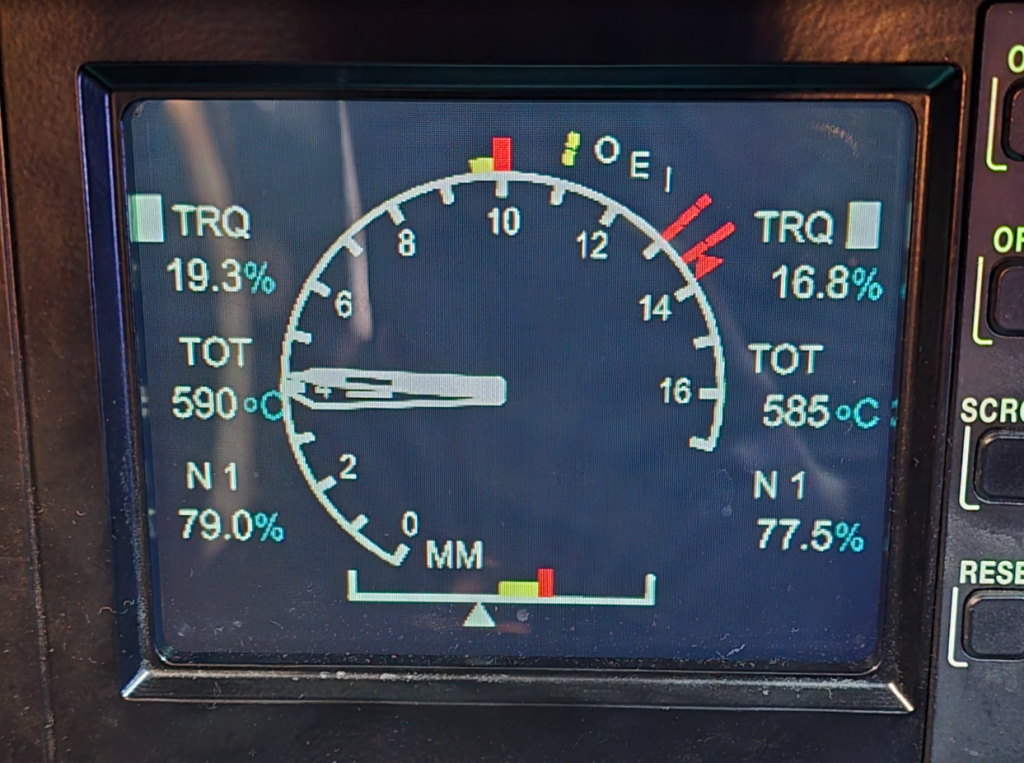
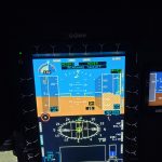
Let’s take an EC135 FLI to get familiar with it. Each engine gets a needle:
- A solid white needle – number 1 engine
- A hollow white needle – number 2 engine
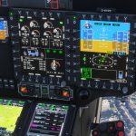
The parameters we have been discussing are down each side. The magic of the FLI is that any of these three parameters can drive the needles. In the example below the torque is driving the needle and this is shown by the white block. The power ranges are colour coded with some limited annotations. 10 FLI is the take off power limit and 9.5 the maximum continuous limit. The pilot has no need to remember what torque, TOT or N1 this relates to. Very straight forward. The needles are normally matched.
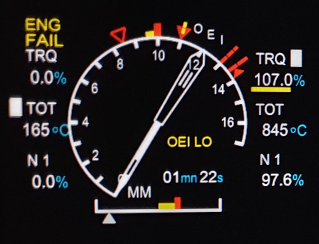
Following an engine failure, the dead engine needle drops away. The remaining engine enters the OEI range with a timer and yellow underline and an ENG FAIL caption appears on the dead side. Really easy for the pilot to interpret…or is it? We will come back to that.
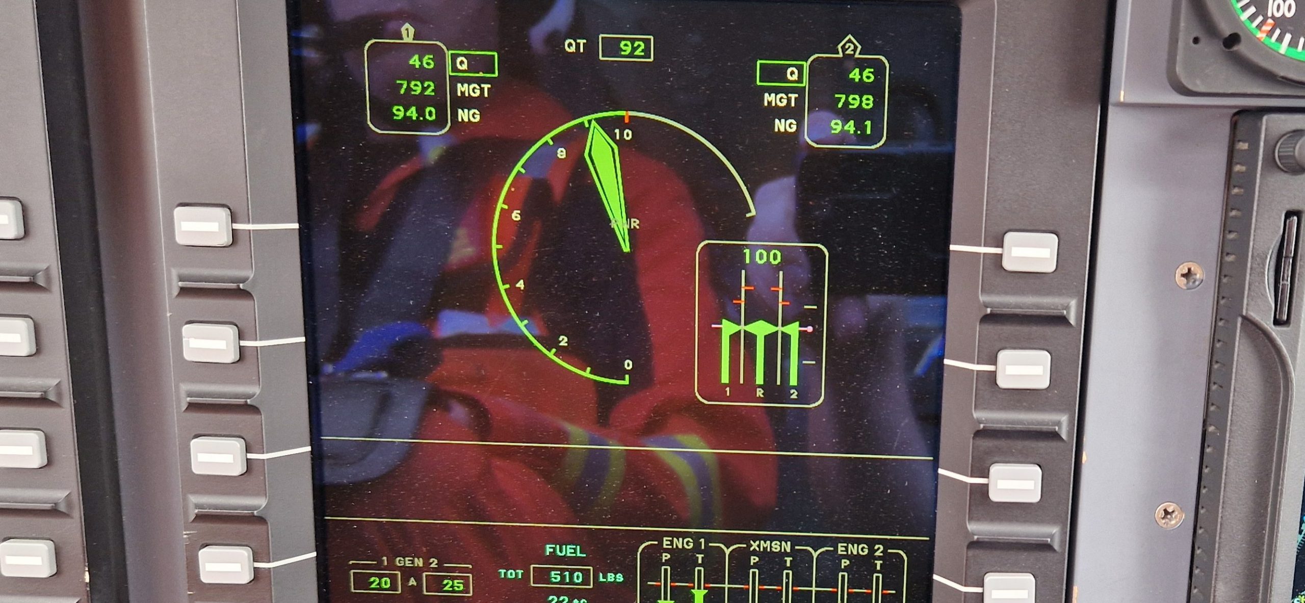
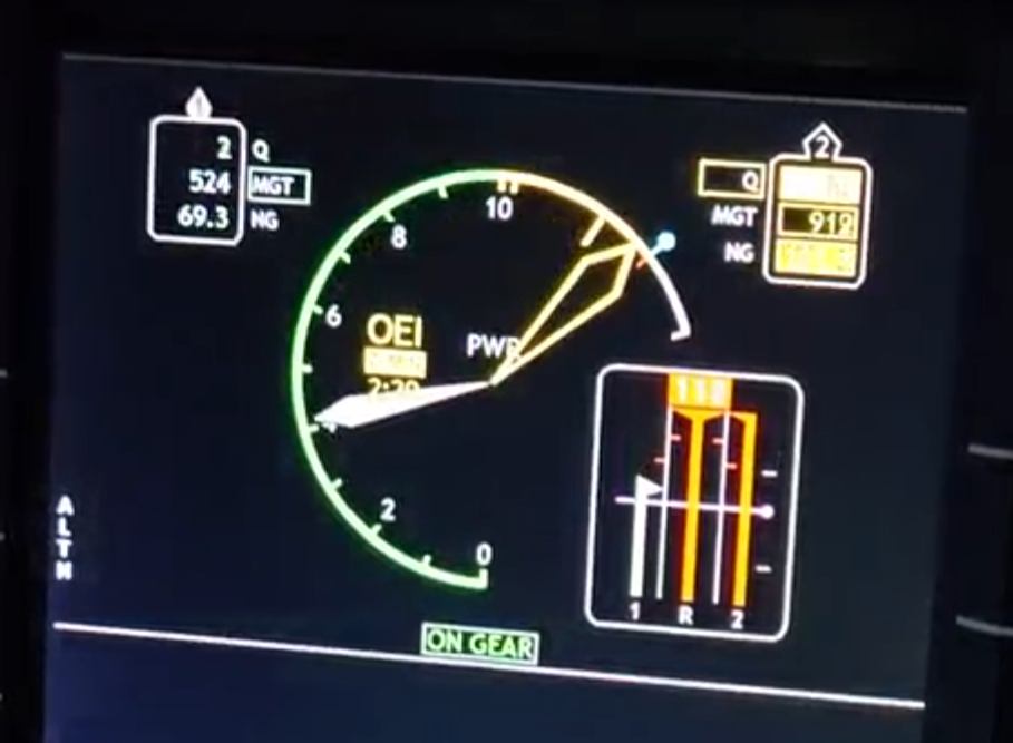
Bell 429
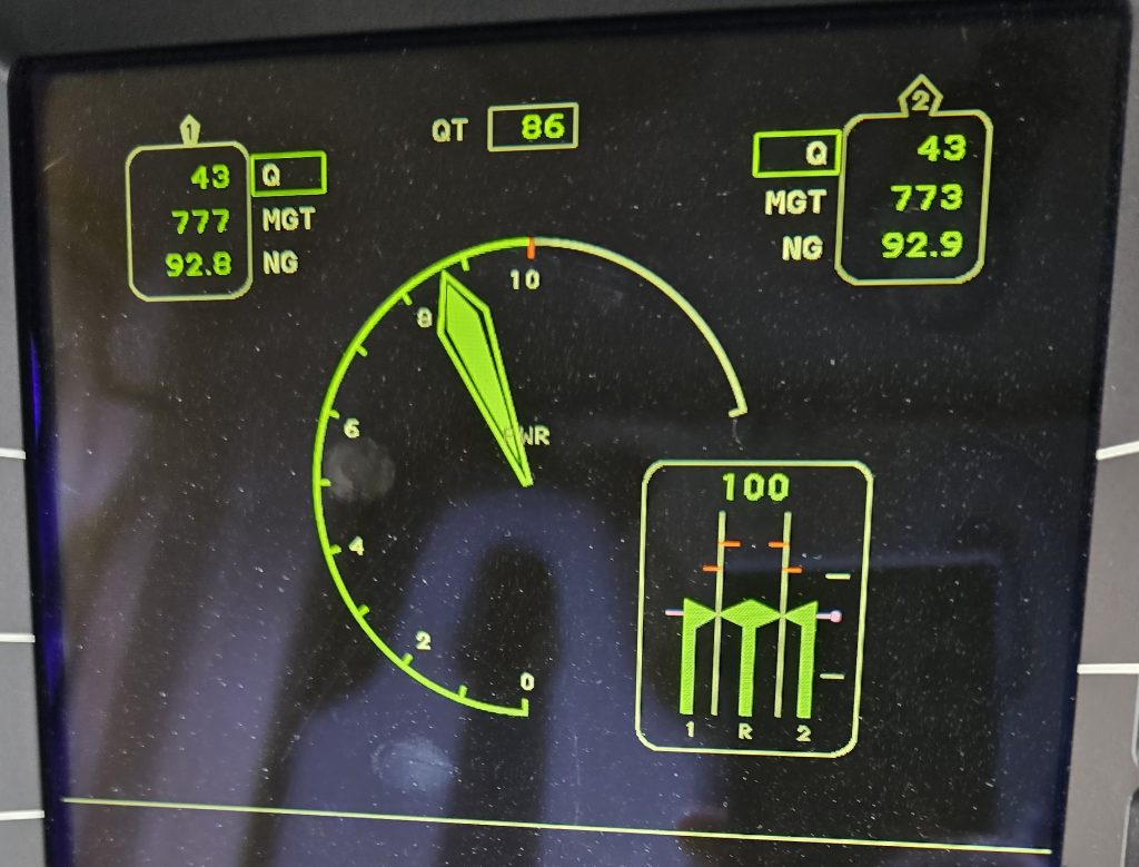
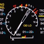
The Bell 429 has a similar logic for its PSI display. A refinement of the Airbus FLI is colour coding – the needles are coloured to reflect their operating range. The driving parameter is boxed. One very different element is that rotor speed and turbine speed are shown close by. This is a useful addition as we will see shortly.
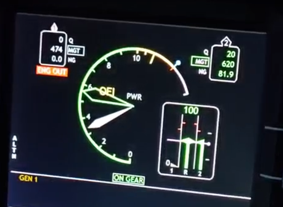
Following an engine failure, the logic is similar to the Airbus FLI. The dead No1 engine is low (and grey) with a clear ENG OUT caption. An OEI symbol is also displayed.
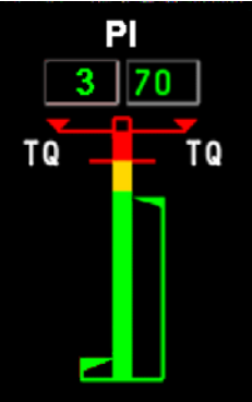
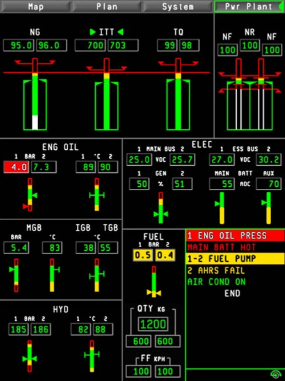
AW139
The Leonardo has ancestry from both Bell and Agusta Westland so it is unsurprising that it takes cues from both. On AW139 the critical big 3 engine indications are brought together on a fixed strip gauge on left of the PFD. This Power Index (PI) can be driven by TQ, ITT or NG in a similar way to the FLI and PSI described already.
In all three types of display normally both needles/PI are matched. When we have an engine failure, the needles split with the dead engine being the lower one. So the low engine is the dead one right?
FLI and Engine Malfunctions
Abnormal Indications
Let’s now look at a Bell 429 PSI display of a different emergency. In this case one engine is responding abnormally in power due to a fuel flow issue. Now the high engine is again in the OEI range, but in this case the rotor speed is well above limits – it would sound horrific and the pilot would be correct in shouting “torque split”! The response is to contain rotor speed by raising collective and shutting down or taking manual control of the engine. See how the co-located rotor speed gauge helps? But so far the FLI/PSI seems to be helping with issue diagnosis. What is the problem?
The low engine is not always the bad one!
Needle split vs torque split
On an FLI/PSI the needle can be driven by any of the 3 major parameters. This is normally torque, but what if that becomes unavailable? Let’s fail a torque sensor. Now we can on this EC135 that the blocks are on different parameters. the needles have a very minor split as the scaling of the needle for TOT and TRQ is slightly different below 10. No problem, it’s fairly obvious a sensor is causing the problem. But it is not a torque split! It is actually a needle split and actually is not a huge problem (just use the other torque gauge for keeping in limits). Note – probably better to state “PI split!” on an AW1391.
Never say “torque split” for an FLI/PSI – say “Needle split!” then work out why
FADEC problems
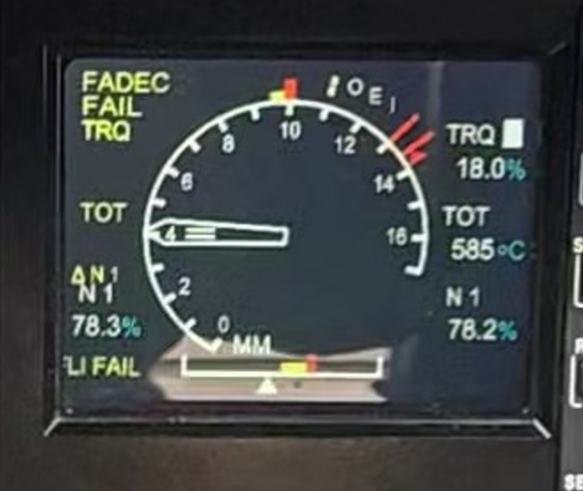
Normally hand in hand with an FLI there is a FADEC in control. Should the FADEC fail, the FLI should show us this in a clear way. Firstly the EC135. As shown below there is a caption for FADEC FAIL and the bad engine’s needle has disappeared entirely. Again fairly clear which engine is misbehaving.
Overspeed vs overtemperature
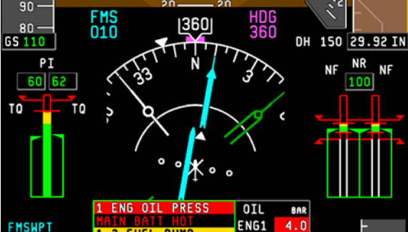
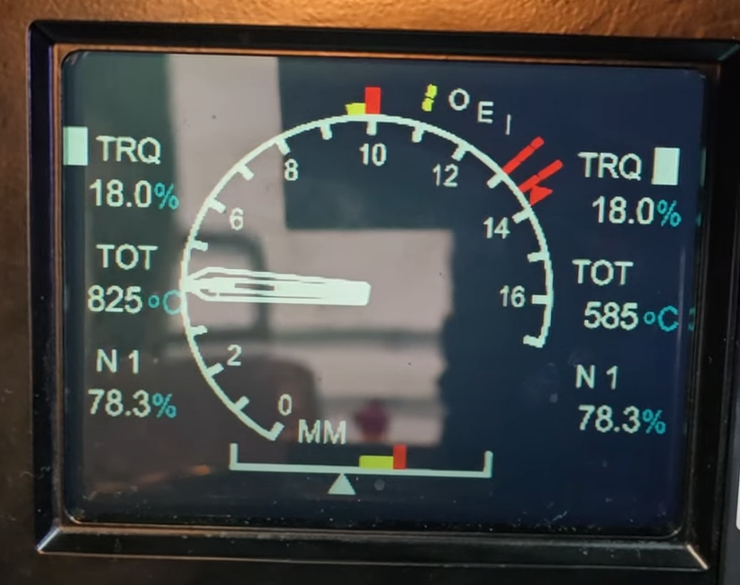
Now we will up the stakes. Imagine an engine that is getting hot. The TOT is rising but everything else is stable. This would jump out wouldn’t it? Nope. Take a look at the FLI below. At a glance the aircraft is healthy, matched needles, both on torque, no underlines in red or yellow. What about the No 1 TOT – yikes, it’s hot but it is not the most limiting parameter nor is outside limits so no change in the display so we miss it.
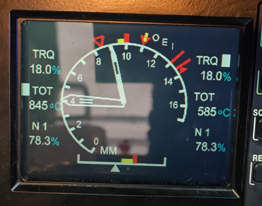
We’ve missed it so the situation develops. Sudden just a few degrees warmer and suddenly the TOT is the most limiting parameter (the block has moved). The pilot calls “torque split!” and incorrectly interprets the No 2 engine is failing (but note the ENG FAIL is absent). Due to startle, the pilot delays his response…
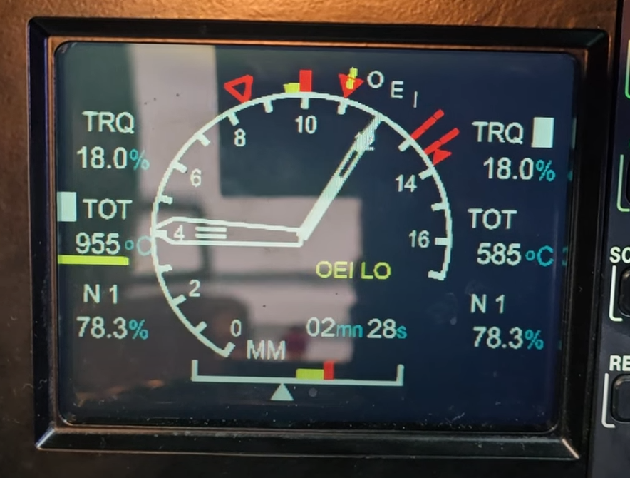
The engine gets still hotter and the No 1 enters the OEI range. The rotor speed has not budged as the torque’s have not moved so it does not sound like a runaway. Note still no ENG FAIL but otherwise it looks like a number 2 engine failure at a glance. But with a bit of care we can identify this needle split is a badly behaving No 1 engine. This would have been much clearer on a separate set of displays – the FLI is not perfect.
Following a needle split you need to carefully work out which engine is misbehaving before acting
Incidents
To illustrate what can go wrong, several incidents need to be examined. The first is a fatal accident in the USA when an EC145, with an FLI very similar to the EC135 was lost following the shutdown of the wrong engine by the pilot after a malfunction. This type of incident is known as Propulsion Systems Malfunction and Incorrect Pilot Response (PSM+ICR). See this paper for where that term was derived.
EC145 C2 engine bearing failure
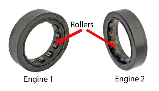
The incident involving N146DU is covered in great detail by the team at Aerossurance. Take a look at the article here: Fatal US Helicopter Air Ambulance Accident: One Engine was Failing but Serviceable Engine Shutdown – Aerossurance. In summary, an oil line got blocked inside the engine leading to the breakdown of one of the hot-section bearings in the engine:
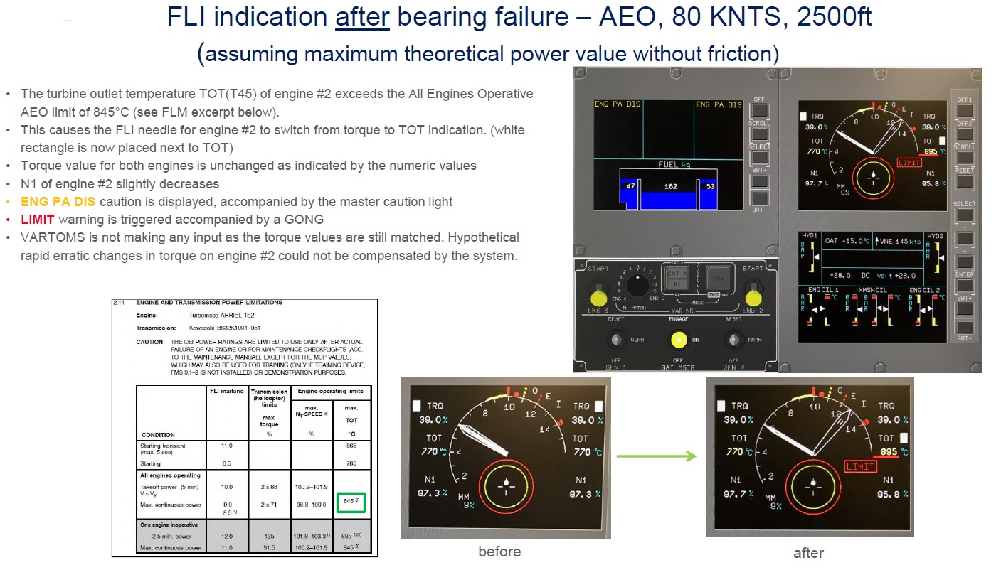
This led to the engine temperatures rising. Take a look at the FLI change. The No 2 engine looks at first glance to be producing much more power than the No 1 engine – a closer inspection reveals it is really hot with torques matched.
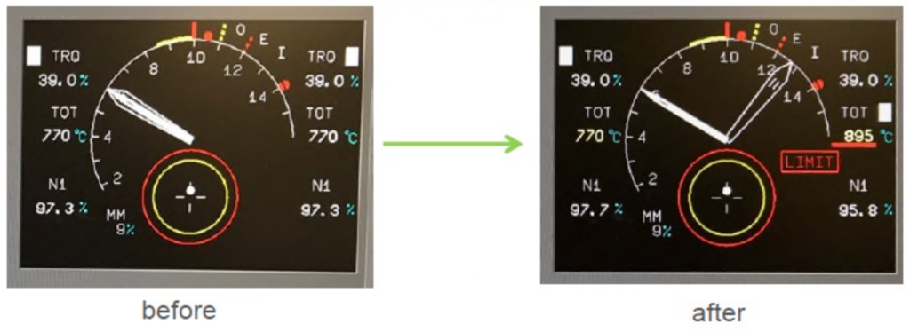
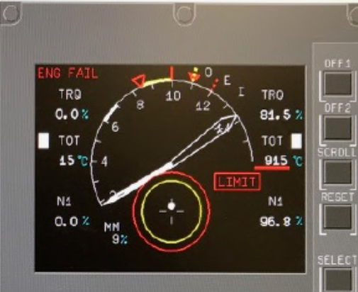
The pilot selected the No 1 engine throttle to full shutdown, possibly believing the low engine was at fault. Note at this point, the temperature looks very high and well above the normal temperature limit for AEO at 845 C – the needle is a long way past 8.5 FLI – normal AEO continuous. Following the shutdown of the “good” engine, the FLI looked like this:
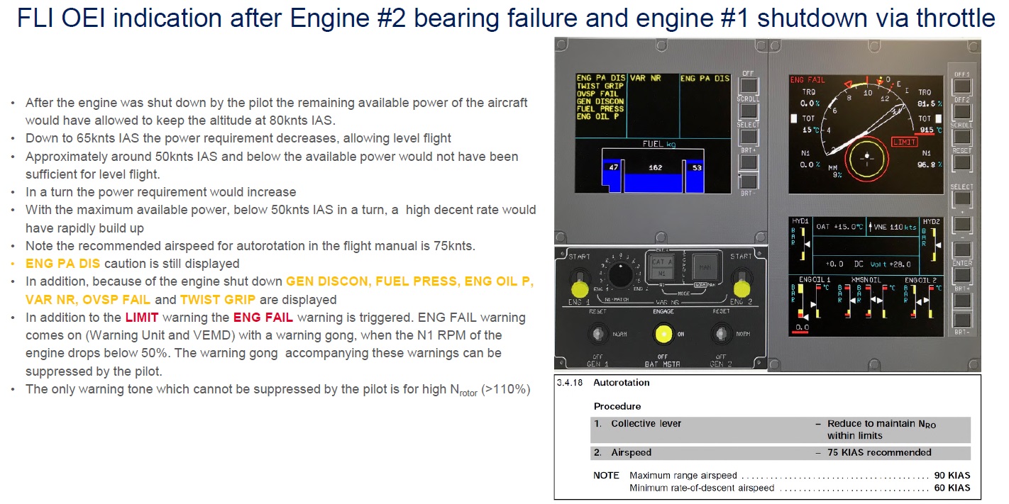
Now the FLI appears to show a normal single engine failure with TOT only a little way above the OEI limit of FLI 12. This unfortunately confirmed his incorrect selection.
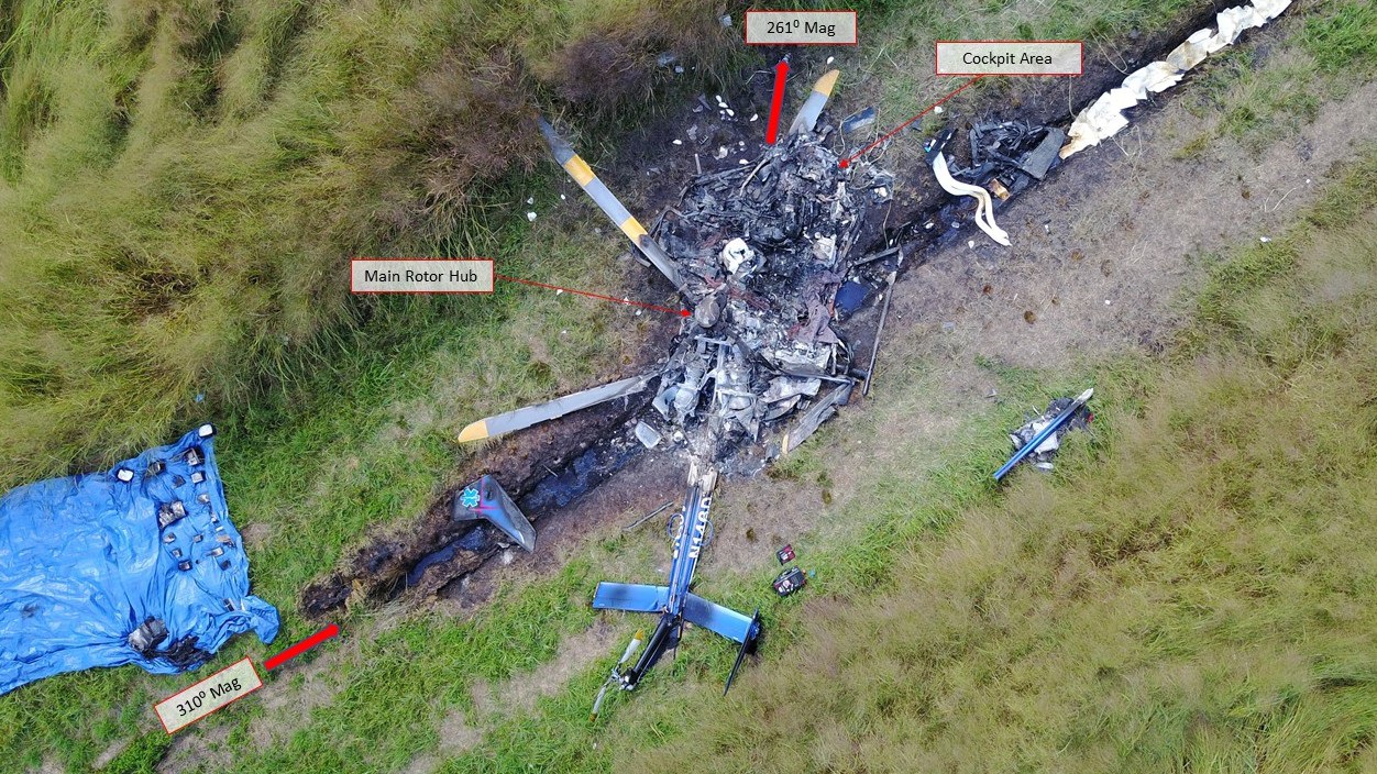
Unfortunately, shortly afterwards the very overheated engine and destroyed bearing failed catastrophically. Autorotation was not achieved and the crew were all lost.
Bell 429 wrong engine shutdown
The next incident is on a Bell 429 PK-WSX in Indonesia – see the final accident report. In this case, the engine control system experienced a malfunction which was recognised by the aircraft systems as a ECU failure. This generated an ECU warning and unlike the EC135, both needles remained displayed.
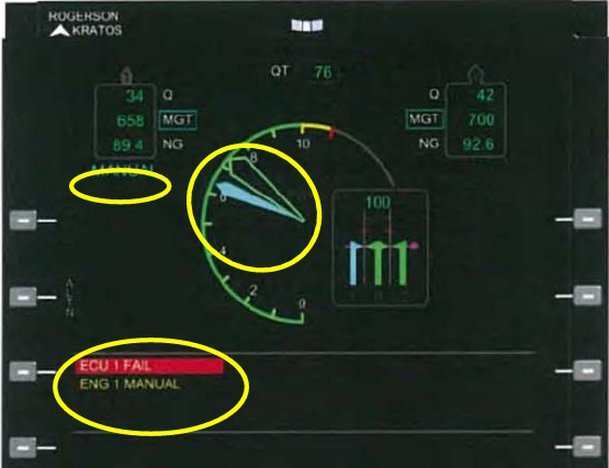
From this display, it appears to be clear that the No 1 is experiencing a malfunction. The cautions and abnormal (cyan) colouring are on the left. However for unknown reasons the pilot responded by manipulating the No 2 engine. He then asked the engineer in the left hand seat to confirm which engine had a problem.
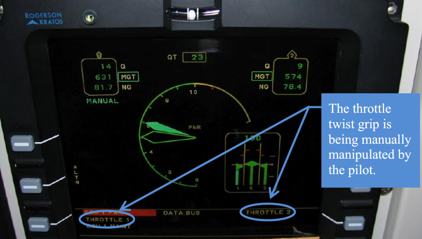
Unfortunately, just as the pilot asked his engineer which engine was malfunctioning, he had moved the No 2 throttle generating a new caution – “Throttle 2”. The No 2 engine was now the “low” engine and the engineer saw a caution on the right No 2 engine and confirmed it was a No 2 engine problem. The confused pilot now switched back and forth between both throttles, neither of which was high enough to sustain normal flight. The aircraft did not maintain altitude and crashed short of the intended landing site, killing a pedestrian.

Crash of PK-WSK – Elshinata.com
Engine Malfunction Strategy on Helicopters
Theory
So what strategy should be used with engine malfunctions on FLI/PSI helicopters? A logical sequence must be used to bring the situation under control and applies equally to single pilot operations or multi-crew operations.
Firstly, the issue must be alerted to the crew or even the single pilot to themselves. This should be through a call to highlight the FLI needles are not coincident (again make it appropriate to the aircraft – so “PI split” on AW139):
“Needle Split!”
Now the situation is highlighted, the next priority is to work out if immediate action is needed. Some pilots call “Check for signs of fire”. This is a hangover from much older machines without a fire indication. Nearly all modern machines have a fire indication. A better call is:
“Check for dangerous indications”
This covers a multitude of issues – does the NR need to be brought back in limits? Is there a need to enter autorotation because both engines are malfunctioning? Is the remaining engine after an engine failure also about to fail?
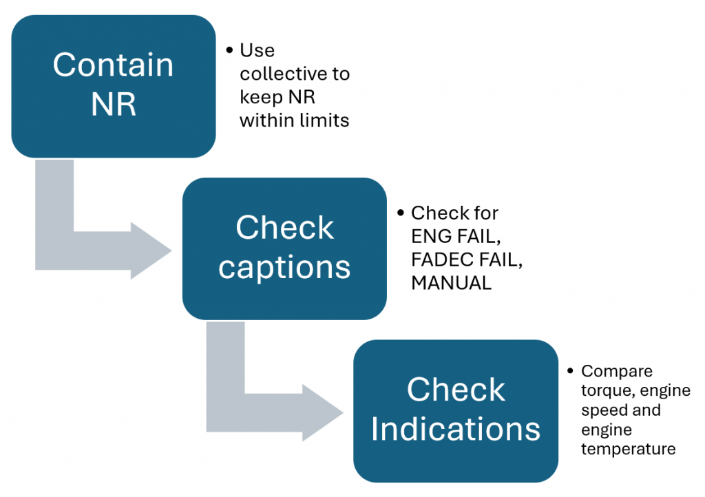
This needs a logical, prioritised process. The most threatening situation on helicopters is governor malfunction leading to rising rotor speed or a complete loss of power leading to low NR. This needs to be contained with collective. Then the captions on the FLI need be checked (eg ECU FAIL, MANUAL) and finally the other indications need to be compared.
With this process completed, then action can be taken. All critical switches must be confirmed before operation. When we say “critical switches” this must include the throttles or power select levers. This would have prevented the accident on PK-WSX.
Application
Now we can apply the technique to a new situation. In this case we will use the Bell 429.
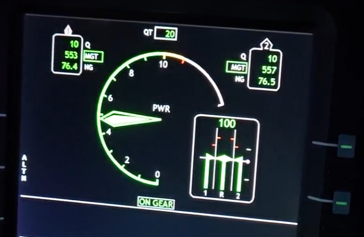
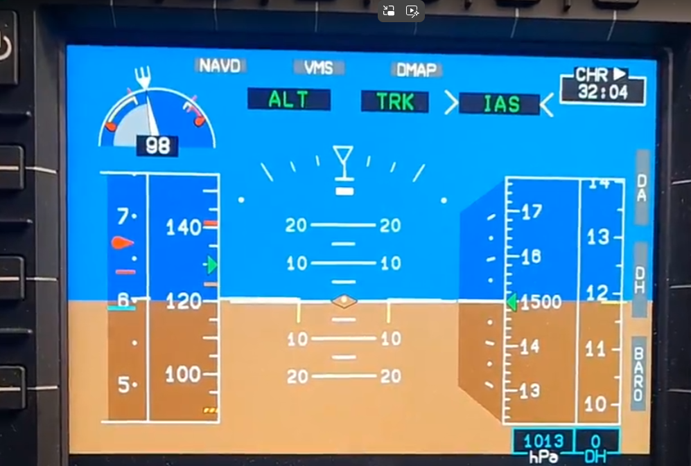
The normal display:
Then without warning something does not look right:
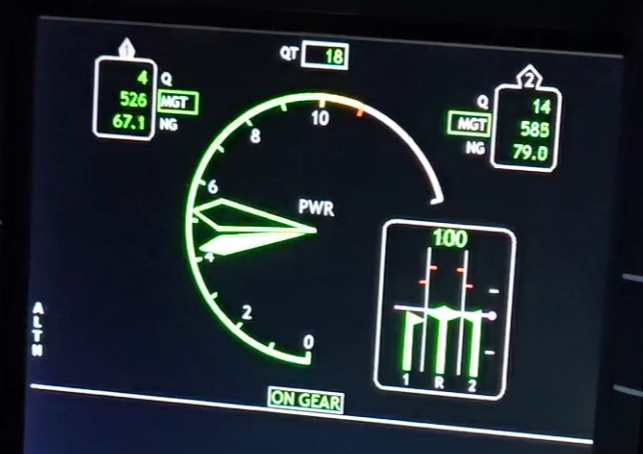
The pilot calls:
“Needle split – check for dangerous indications!”
- Contain NR – The pilot looks inside and notes the rotor speed is stable at 100% – the collective can remain where it is and NR is contained.
- Check captions – The pilot can see no ENG OUT, ECU FAIL or other abnormal captions – no help there
- Check indications – The pilot looks at the big 3 engine indications – all three are dropping – right now it feels like an engine failure but without the ENG OUT…hmmm
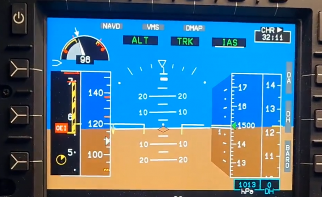
After a few seconds the indications stablise:
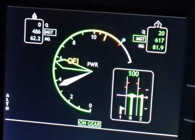
. The pilot reviews the dangerous indications:
- Contain NR – NR still stable but the left turbine speed has fallen
- Check captions – Still no captions – in particular no ENG OUT caption
- Check indications – The indications of Q, MGT and NG are all low but critically the No 1 engine is still turning – it is an underspeed.
Now the pilot can confirm a No 1 underspeed and conduct the correct procedure. Through a logical process no panic ensued and the right diagnosis was achieved using the FLI.
Improving Training on FLI
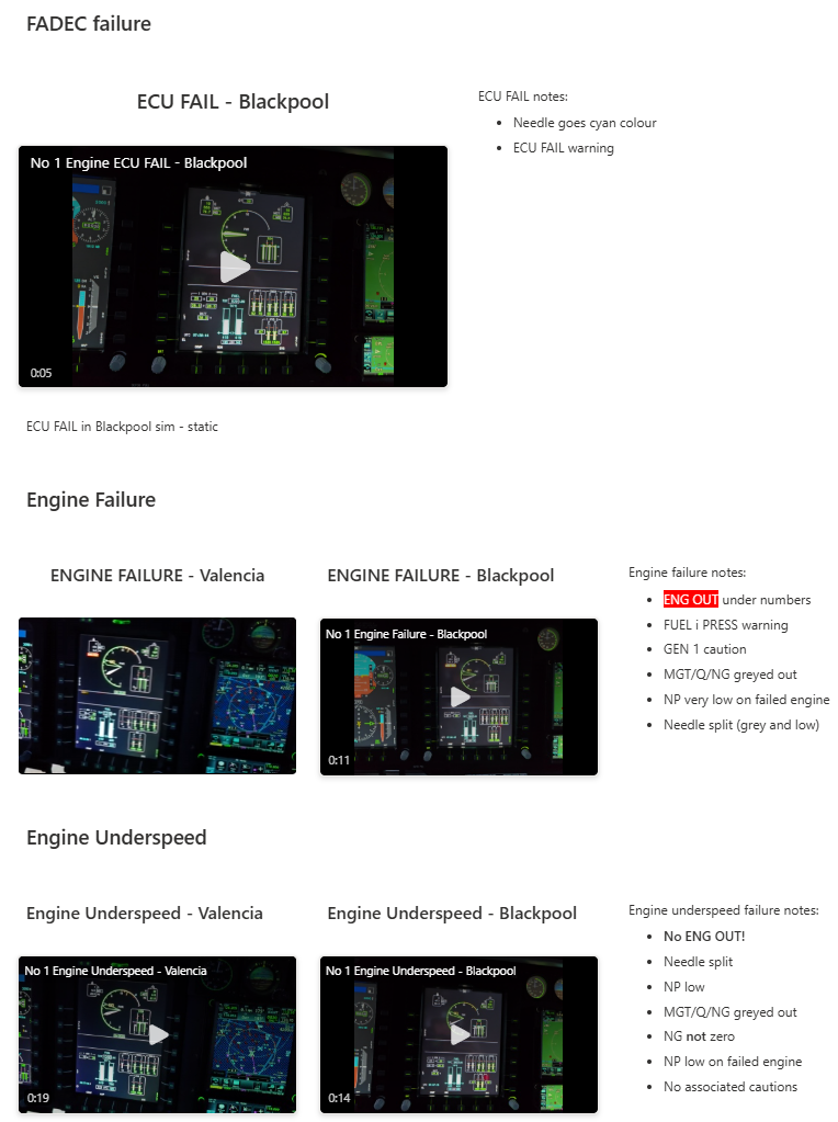
Training for engine malfunctions requires well structured training and should include a suitable simulator whenever possible. See our article about the Broward County EC135 accident for what might occur without suitable simulator practice.
However, simulator time is expensive and may only be visited every 6 months or longer. It may be really helpful to capture some samples of engine malfunctions to review in the briefing room back at base. Below is an example of what you could create on an internal website from one operator. This collection of training videos is particularly beneficial for technical crew who may not go to the simulator as often.
Next Steps for the FLI
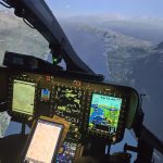
The field of power display on helicopters is never static with many innovations coming on line. Of particular note is the Airbus have changed how they use FLI in quite a significant way. On Helionix which is used consistently across all their new-build multi-engine helicopters, the FLI is now a different beast altogether. However, is it actually a regression to the past?
Now located on the primary flight display, it is a moving strip gauge on the left which has collective pitch as the primary indicator (back to the SA330). Thus above it as 60% collective pitch. The limitations appropriate to the conditions are overlaid on the strip and move dynamically (did the Merlin have this right all along?). The rotor speed display is right next to it (just above) which aids with engine malfunction diagnosis.
Following an engine malfunction, the limitations dynamically move to show the OEI condition – note at roughly the same collective pitch we are now in a cautionary range OEI.
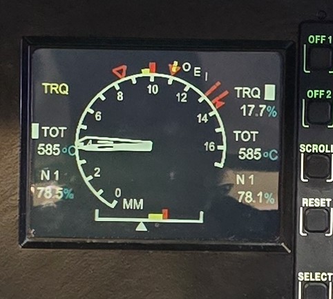
The dynamically moving limits take some getting used to (is the fixed AW139 PI a better way to represent this?) and it is difficult to determine which engine is malfunctioning from the FLI. However, Airbus have split the big 3 indications (TRQ, TOT and N1) onto a separate display as shown below – note this is not from the same emergency (the engine failure has switched sides!)
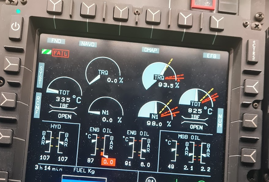
This supports the diagnostic process already outlined. The FLI is only used for maintenance of limits with the parameters separated to allow deeper diagnosis in slow time. It works really well.
The AW139 provides similar information on the POWER PLANT – MAIN page – it certainly seems to be the right path to follow in cockpit design. Strips or dials – which work best for this? Perhaps a future article!
Conclusion
The dial-type FLI can be really easy to use and are arguably easier to interpret than the later Helionix-type FLI but they need to be used carefully. A logical process must be followed:
- “Needle split”
- “Check for dangerous indications”
- Contain NR
- Check captions
- Check indications
Hopefully this will prevent any future PSM-ICR incidents.
Take a look at some of our other articles…
- Unfair Skies: Restrictive helicopter instructor rules and how to fix them

- How to create an instrument rating instructor (IRI) – A helicopter anomaly

- The evolution of Category A Helipad procedures – A strong foundation for VTOL to learn from?

- Strips vs dials – Which is better?
- Under the weather – are UK HEMS weather rules broken?

- Mastery of the GTN 750 – Ten things you should know
- Checking anomalies – The weird requirements of helicopter proficiency checks
- It’s all about the switch – How helicopter designers need to think about the human in the cockpit
- Engine Failure Training Mode – A safety tool that will punish the unwary
- Automated take offs – Pointless or are they the new standard?
- Keeping up with the Norwegians – Six amazing innovations for UK HEMS
- LNAV/VNAV (SBAS) – Are they approved for use in the UK?
- Helicopter 2D IFR approaches – Is CDFA the best choice?

- Understanding Helicopter Flight Manuals – Everything you need to operate safely

- Post Maintenance Flight Tests – How to avoid fatal traps

- First Limit Indicators in Helicopters – Deadly mistakes to avoid
- Bad Vibes – How to report vibrations on helicopters
- Autopilots, cross-checks and low G in helicopter unusual attitude recovery
- Expert site surveys – Improving the assessment of onshore landing areas
- Lights, helipad, action! The problem with new helicopter pad lights
- Helicopter on Fire – Could accident investigators have learned more?
- The Ultimate Medical Helicopter – Selecting the right machine for HEMS
- Deconfliction in HEMS operations – Practical methods for keeping apart
- HEMS Landing Sites – Reliable places to drop your medics

- Planning to fail – The perils of ignoring your own advice

- 2D or not 2D – How much room do I need to land a helicopter?

- What is your left hand doing? How to use a 3-axis autopilot on helicopters

- My tail rotor pitches when it flaps! Why?
- Practical ILS explanation for pilots – the surprising way they really work

- Slow Down IFR! Are you speeding on the ILS?

- It’s behind you! Helipads and obstacles in the backup area

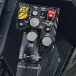
- EC135, Checklists and the “Red Button of Doom”
- Thanks to our Spanish friend for pointing this out! ↩︎
Leave a Reply