
There are many switches, levers and controls in a helicopter cockpit. Each has a purpose and each needs to be carefully designed to fulfil its purpose and be easy to use. However, designer also needs to consider the human factor to ensure the right control is used at the right time but is protected from inadvertent operation.
Many of our aviation regulations today are written on the basis of years of painful experience from accidents and incidents and this is particularly true of cockpit design. There is a vast body of work done on human-centric cockpit design so this article is just to serve as an introduction.
We first look at some of the underlying rules and regulations which govern the basics of designing a control or switch. Then, using real world examples from helicopters, we look at how learning from experience sometimes needs a little work!
Let’s get stuck in!
Rules for designers
There is a considerable body of knowledge of aviation cockpit design, built up since the days of the Wright Flyer. Through experimentation and tragic accidents, some general design principles and guidance that are now captured in the regulations used when designing a helicopter. There is some scope for innovation (think side-stick controls on Airbus airliners) but some rules are written in blood and it’s not a good idea to deviate.
CS, FAR and AC
For the UK CAA and EASA the design regulations are laid down in the Certification Specifications (CS). For helicopters it’s CS-27 for helicopters up to 3175 kg and CS-29 for larger helicopters. The CS are closely aligned with the equivalent FAR-27 and FAR-29 for the FAA in the USA. Indeed they are so closely aligned, that explanatory material for FAR-27 and -29, called the Advisory Circular (AC) 27 and 29 respectively, are just referenced directly by the UK and EASA.
CS-29
For this article we are going to use the EASA CS-29 as an example as it includes the CS-27 rules and we are going to discuss big and small helicopters. The rules pertaining to cockpit design are unfortunately not grouped up together but numerous cross-references in the text aid with navigation. To get a feel for how it works let’s pick out some basic rules and give some examples.
Upwards and Forwards
There are some fundamental concepts that need to be established first so that a designer has a framework to work from. This can be as simple as how something responds if a control is moved in a certain direction. Take the cyclic control as an example. Moving the cyclic left rolls the aircraft left. That is a basic convention of helicopter design captured in CS29 and AC29
Let’s take that a step further to the beeper trim switch. Which way should the pitch datum be moved if the pitch beeper trim is moved up? Up is positive so clearly an upward beep is pitch up. No, wait, that’s so very wrong. An upwards beep should of course result in a beep forward on the cyclic and so a pitch down. We need to be really careful with our conventions.
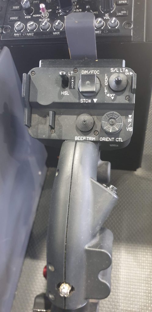
If you really want to make your head melt though, think about which way a steerable landing light should move with an “up” input – should the projected light move up or should the light “dive down” like the trim? On some searchlight systems both options are available on separate controllers in the same aircraft.
Conventions
Fortunately for most controls, AC-29 provides some clear guidance on how all controls should move:
AC29.775 – (2)
(i) Up/forward = on/increase
(ii) Down/aft = off/decrease
(iii) Rotary controls clockwise = up
Some controls need special guidance. Take a twist grip throttle – it’s not really a rotary control from the pilots perspective but a convention is definitely needed to prevent a huge over-torque/over-temperature if moved the wrong way. The language used in CS29 is wonderfully complex:
Twist-grip engine power controls must be designed so that, for left-hand operation, the motion of the pilot’s hand is clockwise to increase power when the hand is viewed from the edge containing the index finger.
CS 29.779(b)
What your instructor told you in basic training also works: “Thumb down, throttle down”
Location, location, location
That covers the directionality of switches and controls but there is a lot more direction for designers. What about the position of the switch? Take a control for a display; where should it be? CS29 says:
Cockpit controls must be:
(a) Located to provide convenient operation and to prevent confusion and inadvertent operation; and…CS 29.777
Convenient
Let’s break that down a little. What is convenient operation? On several helicopters, the rotor speed needs to be manually switched by the pilot from a high setting at low speed to a lower setting as the aircraft accelerates. This needs to be done for every take off and landing so why not put it within easy reach of the pilot?
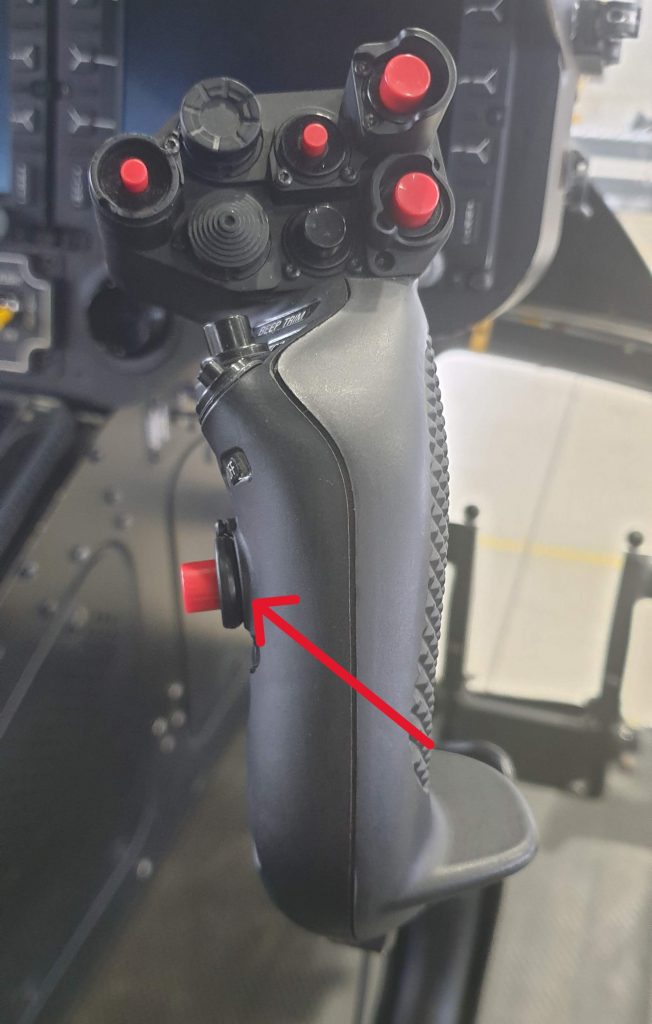
On Bell 429 for example, the switch for controlling the NR datum is on the collective under the pilot’s thumb. Of interest, up is for the higher NR datum (conventions!).
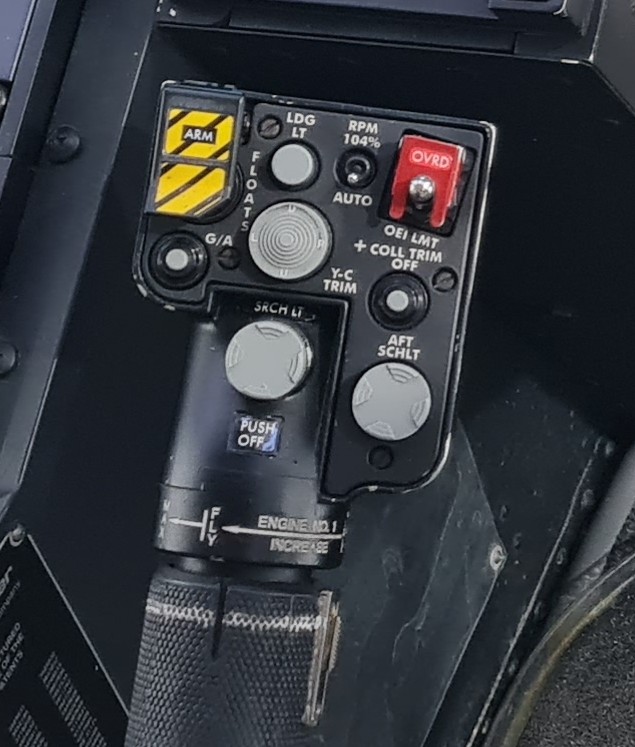
On EC135 T2/P2 however, the button to control the NR datum is on the centre instrument panel. The pilot needs to move their hand from the collective to the instrument panel during a critical stage of flight every single Cat A take off. Convenient?!
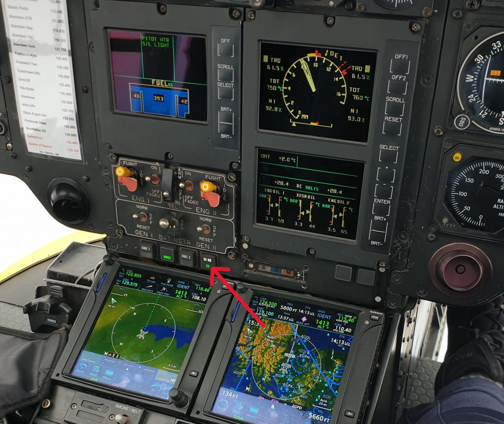
Fortunately this function is automated in later variants (T2+/P2+ onwards).
CONFUSION
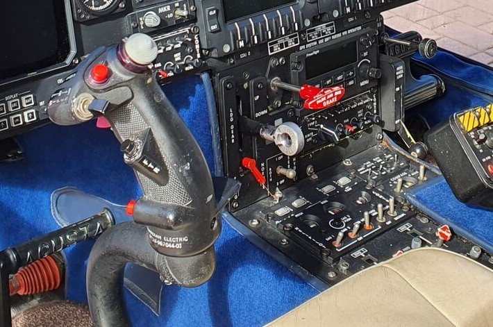
What about confusion? Controls need to be designed to remove confusion. One trick is to make the control feel and look like it’s purpose and to make it unique. For example, the landing gear retraction/extension control on an AW109 is shaped like a wheel – it’s the control lever with the silver wheel-shaped end. Notice it is nothing like any of the other switches or levers near it.
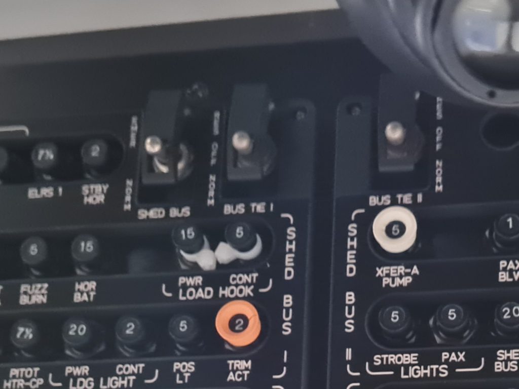
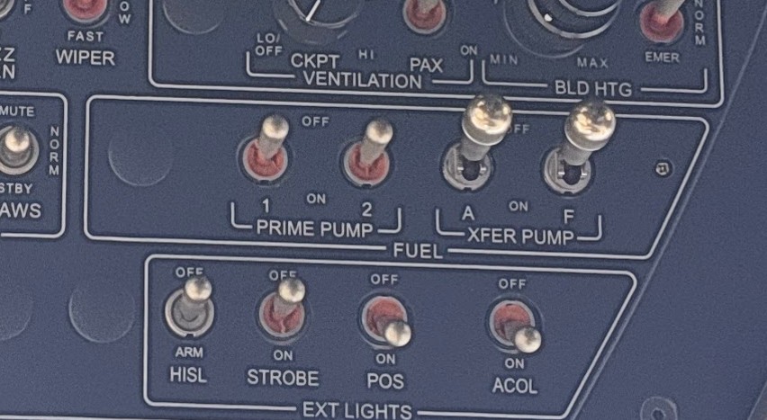
Contrast this clarity with the overhead switches on EC135. Many of the switches on the original EC135 overhead panel look identical. Note in particular, that the PRIME pumps and XFER pumps fuel switches are identical in look and sit right next to each other. The lack of differentiation was highlighted as a factor in the accident involving G-SPAO on 29 November 2013.
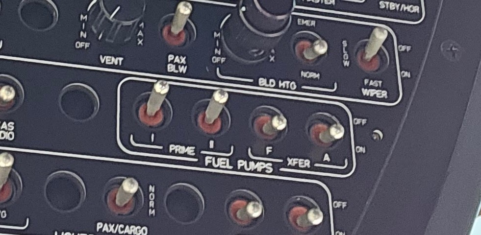
Following the accident, Airbus modified the switches to create a positive discrimination between the 2 pairs of switches in feel and operation (the XFER pump switches need to be pulling over a detent to operate). They did not mandate retrofit of older aircraft however.
InadvertEnt operation
Inadvertent operation of a control can be catastrophic. On helicopters where a twist grip is used to take manual control of the engine’s power, it would be disconcerting if rotation of the throttle to a minimum setting shut the engine down when all you wanted to do was control the engine speed. For example in runaway up governor malfunction. We explore this further in our example.
Guards
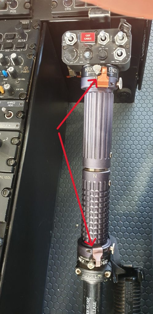
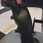
Therefore some manual helicopter throttles have a guard or gate to prevent inadvertent engine shutdown. The EC135 idle stop guard ends up like a trigger under the collective once the throttle is all the way closed. It’s position on the end of each throttle grip means it is unlikely to be pressed accidentally.
Too guarded?
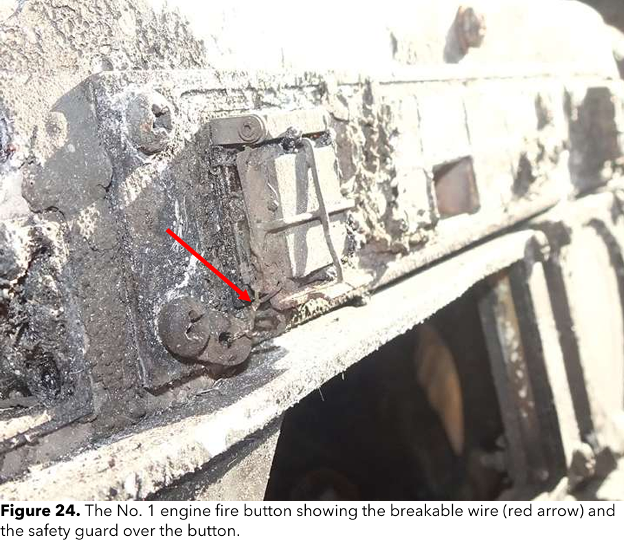
There are unfortunately several examples of guards against inadvertent operation being a little too good. As discussed in our article about the loss of the Broward County EC135 on 28 August 2023, the engine emergency off switch guards were not raised when the pilot attempted to extinguish the fire so the fuel shut off sequence was never initiated. When looking into the aircraft variant involved, it was apparent there was no simulator for it. The pilot had therefore never actually lifted and operated this switch and he is assumed to have pushed the guard rather than the button itself.
Not guarded enough?
Of course, the opposite can be true. Some emergency use switches do not have enough protection from inadvertent operation. On the EC135, as discussed in our first article, “The Red Button of Doom”, the AP SAS CUT button is only protected by a small raised edge. This button removes all stablisation of the autopilot in one press. During the incident involved G-IWRC on 16 September 2007, the passenger in the left hand seat may have inadvertently pressed the AP SAS CUT button with the corner of a magazine, leading to loss of control of the helicopter.
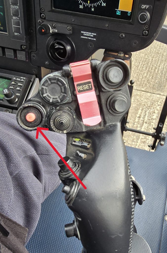
Of note, when originally conceived when the EC135 was a VFR only helicopter, the guard was not critical as the aircraft could easily be flown SAS off. However, once the aircraft was certified for single pilot IFR, the outcome of inadvertent operation is much worse. For Helionix-equipped H135, the button now needs to be pressed twice to completely disengage all stability. Sometimes guards are not the only solution.
Can you reach it?
Let’s now return to CS-29 for another consideration. How does the pilot physically interact with the control The first point of call for guidance is CS-29:
Cockpit controls must be:
(b) Located and arranged with respect to the pilot’s seats so that there is full and unrestricted movement of each control without interference from the cockpit structure or the pilot’s clothing when pilots from 1.57 m (5ft 2 inches) to 1.83 m (6ft) in height are seated.CS 29.777
Can we reach it? Yes we can!
Many pilots fall outside these “norms” but you have to start somewhere. However, this rule is more about ensuring the controls are not prevented from operation by the pilot’s body or clothing. What about whether the pilot can reach the control at all? That’s covered in AC29:
“Equipment should be logically grouped within the pilot’s reach and view and be easy to operate”
AC29 – 29.771
Good practice
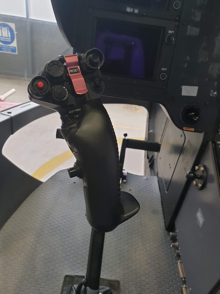
For a comparison lets look at the caution/warning mute/acknowledge. On H145 the button is in 2 places. The first is on the cyclic under the ring finger of the right hand. Easy to reach, but not technically in the pilot’s view!
Alternatively an H145 pilot can also press the ACK softkey directly on the MFD to fulfil the same purpose (great for a co-pilot who does not want to interfere with the cyclic).
Not so good
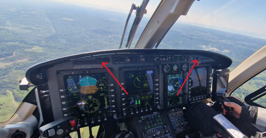
Unfortunately, sometimes the human gets forgotten. On Bell 429, the audio alert acknowledge is only available by pressing he master caution. Since it is mounted only on the eyebrow panel, the pilot must take their hands off the flight controls to do acknowledge it. Not very helpful during a power loss emergency.
That’s a brief introduction to some of the consideration for switches and buttons in CS29. Let’s now look at a specific example of where design did not fully capture the human element and how it has led to incidents and accidents.
Example
As an example, what follows is a series of accidents all related the same lack of protection from inadvertent operation. It is a perfect of not learning sufficiently from each incident and incorporating that knowledge into lessons for future pilots!
Accidental double manual engine
On the Pratt & Whitney (P&W) engined EC135, the engines are normally controlled by a single channel Full Authority Digital Engine Control (FADEC). As a backup in case of FADEC failure, manual twist grip throttles are provided on the collective. Whilst on Turbomeca engined EC135 you can move these throttles a small amount without reverting to manual control, on the P&W variants, a movement of the throttle out of the neutral detent, immediately puts the engine into manual control. A reset procedure is needed to return to automatic FADEC control.
N44NY
On 3 December 1998 an EC135 P1 N44NY was conducting news gathering flights. During manoeuvring the helicopter encountered some wake turbulence. The pilot instinctively tightened his grip on the controls whilst he flew out of the encounter. In doing so he inadvertently moved both throttles out of the neutral detent placing both engines in manual. The engines subsequently exceeded limitations and both failed as the pilot manoeuvred. A forced landing was made into a shallow lake.
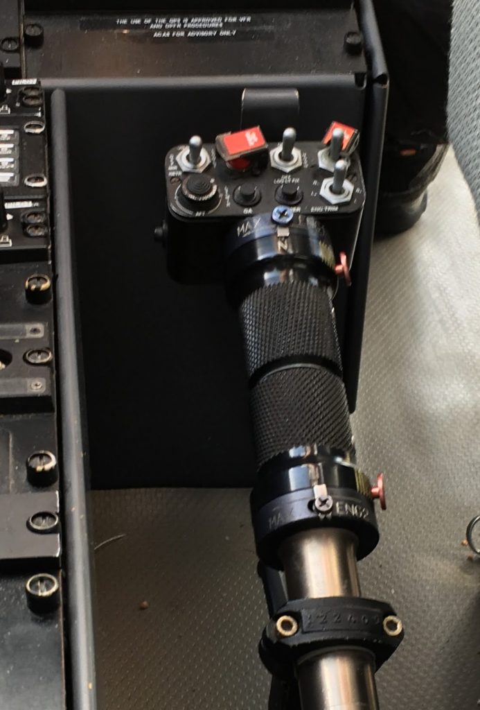
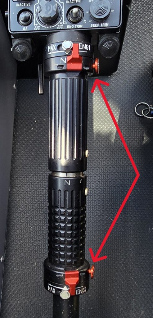
The subsequent investigation by the NTSB identified the pilot and several other pilots could not recall the reset procedure for inadvertent manual throttle activation. It also revealed the throttle friction was too light. Airbus modified the collective for later EC135 variants to introduce stiffer throttles with distinctive texturing and guards to prevent inadvertent rotation of the twist grips.
Problem solved? Retrofit the new throttles across the fleet? Well, no.
N601FH
On 30 May 2006, N601FH, an EC135 P1 was been operated by another pilot with limited exposure to the variant. Again the pilot inadvertently put an engine in manual mode by twisting the throttle, again leading to a forced landing. Subsequent investigation revealed this had occurred to some other pilots on the unit but had not been reported. Ok, problem identified (again), let’s not allow this to happen again. Well, sometimes third time is the charm.
N321SA
On 7 July 2018, N321SA, an EC135 P1 was being operated by a pilot who had most of his experience on an EC135 P2+ with the new collective and throttles. However, he was now assigned to the P1 and he had a brief conversion.
During the flight, the pilot inadvertently twisted the No 1 engine twist grip entering manual mode. Subsequently he also moved the No 2 engine twist grip resulting a double manual situation. During a subsequent descent both engines entered an overspeed condition, There is no overspeed protection on the P1 variant so both engines suffered turbine bursts and failed. Again a forced landing occurred.

The differences training for the pilot was likely inadequate (a self-taught differences package only) and there was no simulator for the P1 variant. This incidents highlights that you have to ensure lessons from earlier incidents are captured for future generations so they do not repeat their predecessors mistakes? Should a fleet wide update to the new collectives have been mandated?
Hopefully learning has now taken place amongst EC135 P1 operators!
Conclusion
This has been a very brief introduction in the complex field of cockpit design. Take a browse through the CS applicable to your aircraft and see if there are any missed opportunities or errors you can capture before they bite!
Now have a browse through our past artices.
- EC135, Checklists and the “Red Button of Doom”
- It’s behind you! Helipads and obstacles in the backup area

- Slow Down IFR! Are you speeding on the ILS?

- Practical ILS explanation for pilots – the surprising way they really work

- My tail rotor pitches when it flaps! Why?
- What is your left hand doing? How to use a 3-axis autopilot on helicopters

- 2D or not 2D – How much room do I need to land a helicopter?

- Planning to fail – The perils of ignoring your own advice

- HEMS Landing Sites – Reliable places to drop your medics

- Deconfliction in HEMS operations – Practical methods for keeping apart
- The Ultimate Medical Helicopter – Selecting the right machine for HEMS
- Helicopter on Fire – Could accident investigators have learned more?
Leave a Reply