
Post-Maintenance Flight Testing (PMFT), Air Tests or Maintenance Check Flights (MCF) can be seen as a simple box ticking exercise after maintenance but can be fatal if a pilot is not adequately prepared. The aircraft is unserviceable until proved otherwise and should be treated as such. In this article we look at the risks associated with this type of flying, the strategies that should be adopted and how it can go wrong.
This article focusses on post maintenance flights of helicopters but many of the strategies can be applied to testing other types of aircraft. This article does not cover developmental or experimental flight test which is something quite different.
If you are comfortable with what Post Maintenance Flight Testing is and want to skip to the good stuff, go straight to General Testing Strategies below.
Contents
- What is Post Maintenance Flight Testing?
- The regulations
- Maintenance Test Pilots (MTP)
- Other Test Crew
- Pre-Flight Test Planning
- General Testing Strategies
- Specific Manoeuvre Guidance
- Post Flight Reporting
- Conclusions
What is Post Maintenance Flight Testing?
Post Maintenance Flight Testing (PMFT) or Maintenance Check Flying (MCF) is a particular type of test flying that is conducted after scheduled maintenance, after fault rectification or periodically to confirm airworthiness. It is not the kind of flight test conducted to certify a new aircraft type or modification. It is also distinct from the acceptance testing done at the manufacturer facility after completion of the build but there is a lot of cross-over, particularly with respect to the procedures used.
The testing is usually conducted in accordance with some form of procedure in a maintenance manual and the tests should be designed to achieve consistent results that can be used to determine serviceability of the aircraft.
The regulations
As with many things in aviation, the rules, regulations and procedures for post maintenance test flying are written in blood. In both the military and civilian worlds a particular accident is often the trigger that causes regulations to be tightened up around this kind of flying.
UK Military
For the UK military it was the loss of a Harrier ZD326 (but thankfully not the pilot) near Laarbruch on 4 February 1999. The experienced pilot was handed an update to the flight testing schedule just prior to flight and he then lost control during a new test point.
The UK military reviewed flight testing in general and Wg Cdr Radley, a very experienced experimental test pilot, produced a report into the conduct of post maintenance flight testing. This triggered an update to regulation which is now captured in Regulatory Article 2220. One of the recommendations of the report was the creation of a Maintenance Test Flying course which available at the Empire Test Pilot School at MOD Boscombe Down (the course content is discussed in this article in the Focus magazine of the UK Flight Safety Committee.

EASA and UK CAA
For EASA/UK CAA, it was the loss of an A320 flying as XL Airways Germany, Flight 888T, plus a non-fatal incident on 12 January 2009 to G-EZJK which triggered change. Flight 888T was completing an end of lease check flight where the crew tried to squeeze in a test in sub-optimal flight conditions at low altitude and could not recover the aircraft after a component failure put the aircraft in a backup flight law. The incident on G-EZJK was a check flight where company procedures, rather than the ones from the maintenance manual were used to guide the crews.

An EASA Rule Making Task led to the introduction of the Maintenance Check Flight (MCF) regulations in the Air Operations Regulation 965/2012. The regulations were broken down into Part NCO for small aircraft and Part SPO for larger aircraft.
Level A and Level B MCF
In both types of operation, the regulations split the types of Maintenance Check Flights into 2 types:
- Level A MCF – Flight tests where use of abnormal or emergency procedures is expected or where functioning of backup system or safety device is required
- Level B MCF – Flight tests other than Level A
The requirements for flight crew, training and operator rules are significantly different between the levels, particularly for Part SPO. This huge leap in requirements can cause a problem. Let’s dig deeper.
Operator Choice of MCF Levels – A Problem Area
The operator of the aircraft is responsible for determining which flight tests are Level A MCF. This creates a conflict of interest which needs to be resolved. On the one hand, the operator wants to keep their aircraft and crews safe but on the other hand implementing the necessary training and restrictions that come with making flight tests Level A is expensive in time and resources. A Level A trained pilot needs to be on hand: Have we trained enough people? Are they current? and so on.
The definitions above are open to several interpretations. The European Safety Promotion Network – Rotary (ESPN-R), provide an excellent set of resources on their website. They provide a sample test manual and risk assessment are offer some thoughts about how to classify flight tests.
Methodologies
They suggest two methodologies:
- Flight Manual section – any manoeuvre not in the “normal” section of the Flight Manual is a Level A – this actually leads to nearly every manoeuvre being Level B with a few exceptions (eg autorotations and intentionally switching off one half of a redundant system like the hydraulics)
- Level of risk – The other method suggests the level of risk if the system fails should be used – this leads to nearly every test being Level A.
For example, Is a SAS stabilisation a backup system? Does testing SAS really warrant the level of training needed for a Level A test. What about an autorotation – that’s an emergency procedure in the Flight Manual – should an autorotation MCF be Level A but its done in training all the time? Is operating close to a power limit Level A (eg EC135 N2 check). This needs some training to achieve safely. That seems to need Level A but it is not abnormal or an emergency.
In any case, responsibility rests with the operator and needs careful consideration and risk management. The step-up to Level A testing is steep but potentially critical.
Maintenance Test Pilots (MTP)
The choice of pilot for any maintenance test flying can be challenging. It may be from a cast of one due to scheduling and rostering but the demands of the task, and in some cases regulation, require something more specific.
The requirements can be broken down into knowledge, skills and attitudes:
- Knowledge – The pilot needs to have a very good understanding of how the aircraft should feel in normal conditions and have the necessary knowledge of the test points to be conducted
- Skills – The pilot needs the right skills to operate the type and conduct the role (eg SAR for winching tests). The pilot must also be able to comminicate their findings to the engineering test (“It’s a bit wobbly” is not going to cut it)
- Attitudes – The pilot should preferably be a volunteer for the role with a high level of integrity and thoroughness. They must also be resilient during emergencies which are more likely in this role.
Under EASA / UK CAA there are some specific requirements for pilots doing Level A MCF in SPO.SPEC.MCF.115 (only the Part SPO requirements are listed – the Part NCO requirements in NCO.SPEC.MCF.125 are much less stringent):
- MCF Level A pilot requirements:
- 1000 hrs on helicopters, 400 hrs as PIC in a complex aircraft, 50 hrs on type
- Completed an MCF training course (which should include simulator training) and observed a live MCF flight
- Recency in MCF is 36 months before recurrent training is needed
Training
The regulations lay out a training course for MCF crews. The course is category specific (eg helicopters or fixed wing) but not type specific. The course should be delivered by someone competent in MCF (eg Euro Flight Test). The contents needs to include:
- Regulations
- Flight Planning and aircraft preparation
- Risk Management
- Equipment and instrumentation
- Cockpit management
- Techniques for test items
- Review of failure cases
- Post flight analysis
There is still a guidance document prodcued by the CAA as CAP 1083 which covers the conduct of “Check Flights” However, it now contains the following warning:
“This Handbook will not be subject to any further amendment, because the CAA is no longer able to offer up-to-date guidance on check flight procedures”
Other Test Crew
MCF can be demanding to fly while recording data. Where possible an extra pair of eyes and hands can be useful. This person is called a task specialist in EASA / UK CAA terms. The person may be another pilot in a multi-crew cockpit or an engineer.
Experience
The extra person needs to have a deep level of knowledge of the aircraft and much have the requisite skills to conduct the test points. Being able to operate any test equipment such as track and vibration computers or sensors is an obvious requirement but less obvious is the need to successfully use a ruler to measure flight control inputs without getting in the way of the pilot!
Training
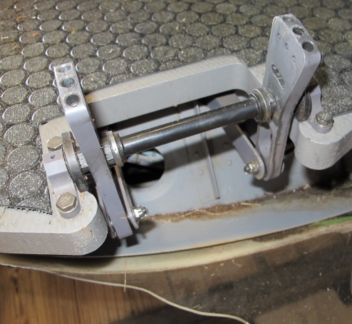
The training for any task specialists should run along similar lines to the pilot’s training and should include simulator training where possible. The pilot should check the recency of the task specialist and provide a safety brief (particularly if they operating in a cockpit seat with dual controls). As can be seen from this picture of a Bell 412 flight test, the track and vibration computer could interfere with the flight controls if not managed correctly.
Pre-Flight Test Planning
Many of the risks of completing MCF can be mitigated on the ground before stepping anywhere near the aircraft. Let’s look at some of the methods of reducing risks.
Flight Test Schedule / Air Test Proforma
The test crew and engineering team need to be very familiar with the flight test schedule, which is often part of the aircraft maintenance manual or a separate controlled document (this is often the case in the military). It is important the crew knows what data is required, in what conditions and when.
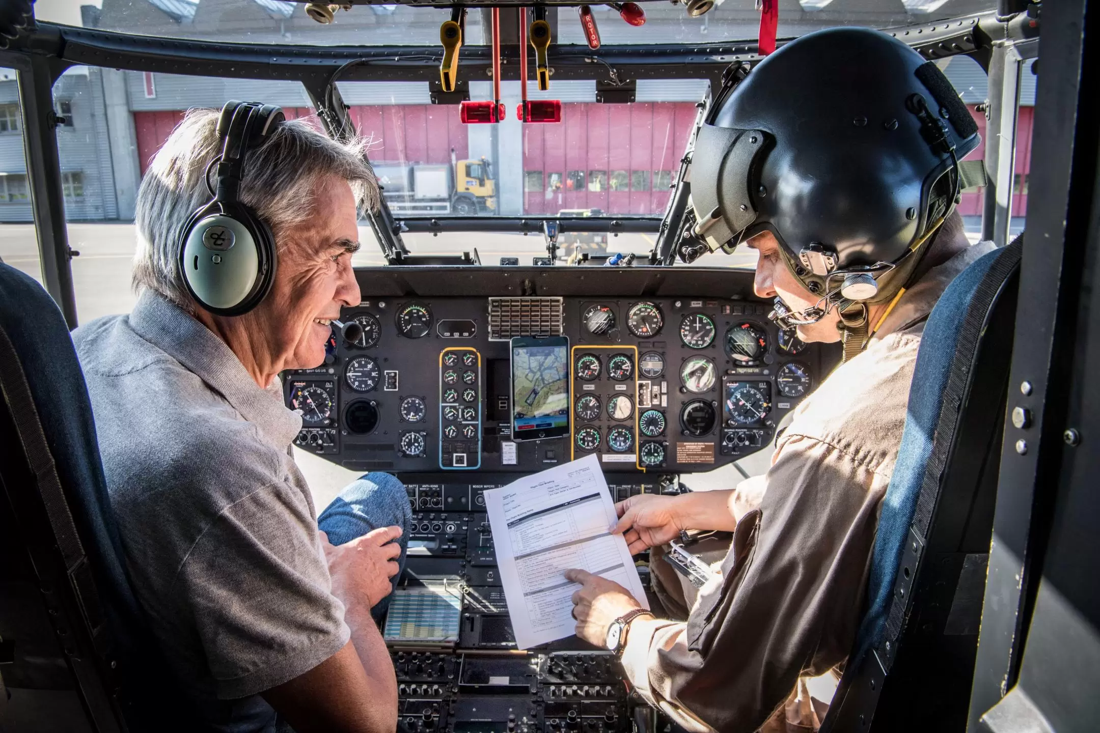
The test schedule should be thoroughly understood and briefed prior to start – RUAG
Unfortunately, the clarity of some flight test schedules is poor. This can be because of the background of the author (eg an engineer writing a flight procedure for pilots) or because of language differences (this occasionally happens with Airbus documents).
It is vital that each operator takes action to engage with the aircraft manufacturer (eg through Airbus’ Technical Request programme) to try to clarify such issues and to try to improve the documents going forward. In parallel to this, operators should consider producing supplementary guidance for crews based on experience of completing the tests. This provides a body of “corporate knowledge” that endures through the life of an aircraft with a company. It is also very useful to create links with other operators of the same type to share knowledge.

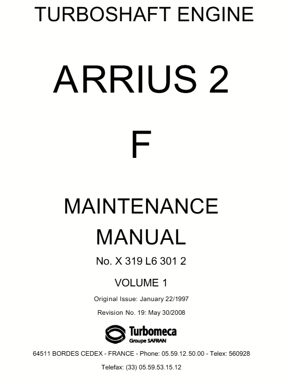
Aircraft vs Engine Manufacturer
A peculiar oddity can occur with testing of the engine and related components. Both the aircraft and engine manufacturer can provide test procedures for the same engine requirement. They may provide slightly different information which can provide useful information to the crew – this is definitely the case for some procedures on Airbus EC135 with Turbomeca engines (such as the now fully automated Preference Injector check).
Optional Equipment
The aircraft manufacturer test procedure is only for the basic aircraft and manufacturer modifications. The aircraft operator and engineering team need to consider if the optional equipment fitted to the aircraft require additional testing or whether installed equipment will modify the extant test procedures.
For example, a hoist might require additional tests. External mounted equipment might change tests completed at high speed, reducing the speeds applicable to test points.
Ad Hoc Testing (Airborne Check)
There are some occasions where a test or check is required that is not documented in the normal way. For example a flight might be required to demonstrate a fault to an engineer (eg a system error that is deleted automatically on shutdown). These types of flight need even greater scrutiny than normal check flights as the lack of structure can lead to the “good ideas” club getting in on the action. Any testing must strictly be within the flight envelope and any conditions approached methodically and incrementally.
How vs What
Many written procedures are strong on what needs to be tested but can be very light on exactly how something is to be achieved. How fast is that collective rise? How fast should that throttle be turned? What weight should the autorotation be completed at?
These questions when uncovered should be included in an operators guide. Building corporate knowledge through SOP or a test manual can help to standardise tests and improve safety
Where to Fly
Where tests are conducted can directly influence the risks associated with flight testing. Helicopters typically operate in relatively close proximity to the ground but flight tests might require some high altitude testing, prolonged flights without turns or large orbits. A good knowledge and comprehension of the procedures should influence the choice of flight area.
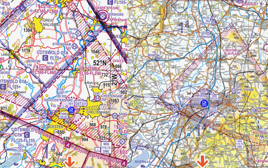
Correct scale?
As an example, in the UK the scale of map used for navigation may need to be different for MCF than normal operational flying. Typically for helicopters, VFR operations are conducted below 3000 ft agl and so the 1:250,00 CAA chart is appropriate. Some test points require the aircraft to be climbed up to 10000 ft. The airspace at this level is not shown on a 1:250,000 chart so a 1:500,000 chart is more appropriate – note the airspace north of Gloucestershire Airport (EGBJ) which starts at FL75 on the left (1:500,000) but is not shown on the right chart (1:250,000). Similar issues can occur on vector mapping (eg Foreflight) if airspace is suppressed about a certain level.
Drifting slowly downwind
It is also important to select appropriate airspace for the manoeuvres to be flown. As an example the airspace north of Gloucestershire Airport is relatively free of airspace at low level so long straight legs can be used for track and vibration testing. However, airborne compass swings require large orbits. A northerly wind could cause the aircraft to drift south during these loops, potentially causing a conflict with Gloucestershire traffic.
On a final point, there is a rule in the UK Rules of the Air Regulations at Rule 6 that prohibits flying over congested areas during test flying. This does not include MCF as the aircraft does have a valid Certificate of Airworthiness.
Risk Management
Risk management for MCF can be completed for each flight or prepared in advance for the whole MCF profile and then selectively referenced for each test point. It is really important to focus on what makes this flight different so that general risk management doesn’t hide the particular risks of MCF. In particular it is important to consider the following points:
- Distractions – reading gauges and writing down numbers may distract from lookout
- Electronic conspicuity (EC)
- Is the transponder itself under test?
- Are normal carry on EC devices available for test flights (eg Sky Echo 2)?
- Conduct of abnormal or emergency procedures
- Is risk of selecting system off mitigated?
- Has adequate training been completed to mitigate risk?
- Are panels being opened or closed prior to departure? Who is checking them?
- Supervision
- Is CAMO aware?
- High level authorisation for flight? (eg by Chief Pilot)
- Documentation
- Is flight test schedule latest version?
- Are all amendments applied?
- Have all the necessary maintenance procedures been completed and appropriate signs off completed (check with CAMO?)
- Operating near edge of flight envelope
- Incremental approach to limiting parameters
- Mandatory recovery actions (eg if certain bank angle exceeded)
- Parachutes, emergency beacons, flight following?
Environmental Conditions
As already discussed, the normal flight conditions for an MCF should be day, VMC. Certain test points may also need particular flight conditions:
- Track and vibration
- Sun – Track and vibration cameras can struggle to function when looking directly into sun. The flight may need to be arranged for legs perpendicular to the sun to minimise this issue
- Turbulence – Bumpy conditions may affect results
- Low speed testing
- Direction – To minimise ground speed it is good to do low speed testing into wind. Is there a useful runway available?
- High altitude power checks
- Clouds – Some test points require long sustained climbs. This may require a day without any significant clouds which may restrict operations until a window of good weather is available. Climbing up through cloud to get clear air is usually not possible as VMC should be maintained during MCF
Mass and Balance
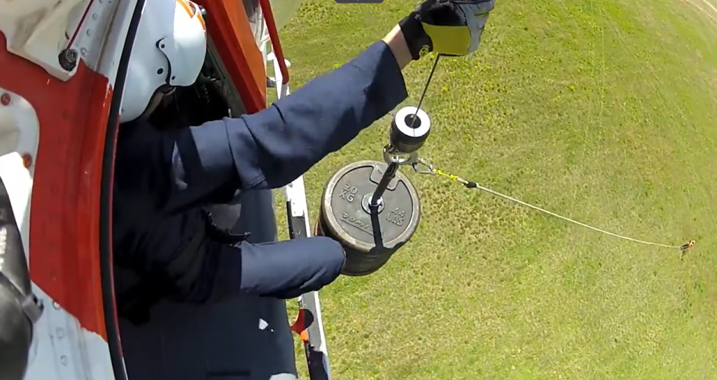
The mass and balance of a helicopter may need to be managed carefully to meet the aims of the MCF. For some test points a certain band of allowable masses must be maintained for the test point.
In other circumstances, such as a ground power check, the aircraft may need to be a certain minimum weight in order to not get airborne during the test. As aircraft coming out of maintenance can be missing lots of role equipment and can be very low on fuel, their overall mass can be very low. This can lead to the aircraft getting airborne with only one engine operating at a test power setting. For example, this means on and EC135, ballast is needed to weight the aircraft down for a ground power. This usually takes the form of any engineer who is in the area. This must be carefully managed, even if “just a ground run” as emergency scenarios and security of the passengers (eg seating) must be considered.

Briefing
A comprehensive briefing is vital to ensure the necessary documentation is in place, the key players understand the task and that all necessary planning and risk management has been completed. The briefing should include the flight crew (including task specialists), the relevant engineering team and any operational staff who may need to book airspace or airfields. The following should be covered:
- Engineering background
- Where has aircraft been – straight from line, from deep maintenance?
- What rectification has been done?
- What test procedures are required?
- What are tests being conducted in accordance with (eg Maintenance Manual)?
- Weather
- Normally day, VMC
- Turbulence levels – very relevant for track and vibration testing
- Light levels – some track and vibration equipment needs moderate light (not too much and not too little)
- Base conditions – crosswind, landing surfaces (in case of emergencies)
- Winds – this may affect how an aircraft gets blown downwind in flight during compass swing orbits
- Enemy action – if testing in a deployed environment
- Risk Management (see above)
- What particular risks presented during required test points?
- Apply TEM for relevant test points
- Crewing
- Right personnel for the tests – trained and experienced
- Aircraft
- Any extra equipment fitted and modification state
- Any missing panels?
- Fuelling or ballast requirements (eg for ground power check)
- Limitations
- Will the testing trigger a FDM event?
- Testing locations and any booking/airspace requirements
- Documentation
- Tech log – what maintenance entries are open
- Check A – has relavent pre-flight inspection been completed
- What needs to be recorded? Who is going to be writing it down?

General Testing Strategies
Before moving onto specific manoeuvres, some core strategies for managing MCF need to be laid out.
Understand why the test is required
It is absolutely crucial for the flight test crew to understand exactly why the test is required. In particular the flight crew must know what systems or areas of the helicopter have been disturbed during maintenance. It is not second guessing the engineering team but rather an application of the mantra “Trust but verify”. No one should be afraid of another professional checking their work.
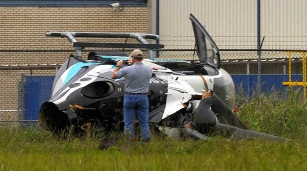
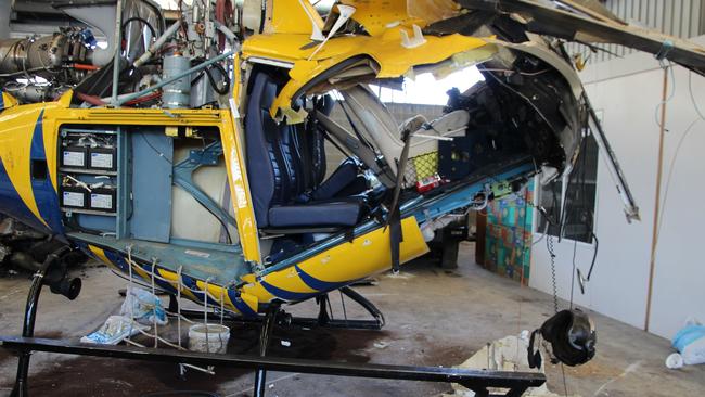
The penalties for paying lip service are severe. On 9 November 2013 an EC135 N911KB coming out of maintenance was taken on a hover test flight. During the take off the aircraft began to rotate 90 degrees left and subsequently spun down the airfield before crashing. It is was found that the yaw pedals had not been re-assembled correctly – the pedals had only been put in the right place but had not been bolted back on. If the pilot has asked what had been disturbed, they might have paid special attention to the pedal attachments.
Checklists
For many pilots on single pilot helicopters, operating their aircraft can become second nature with no need to refer to the start up checklist when getting airborne. An MCF is not the time for this approach. For an MCF the pilot should get the normal checklist out and complete the full start and systems checks from the cards. Not only will this ensure the pilot has a chance to review their own process but it ensures the aircraft is comprehensively checked.
Going back to the incident on N911KB, if the pilot had completed the full normal start procedure in accordance with the cards they would have completed the hydraulic checks. This includes a check the yaw pedals operate normally which would have highlighted before take off they were not attached correctly.
“When starting and shutting down the aircraft for a Maintenance Check Flight use the normal checklist and do not rely on memory drills”
Incremental
Many test points might require the aircraft to be manoeuvred up to a particular limit. This is particularly true for low speed handling. The test profile might say “Fly up to 35 kt sideways and backways to confirm handling is adequate”. The pilot should approach these test conditions in an incremental way, proving the aircraft handles well at lower speeds before building up to the actual required limit.
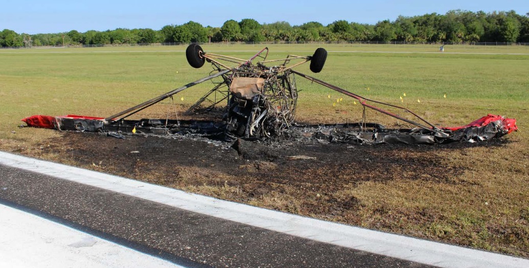
Take the example of a maintenance check on a classic PA-12 aeroplane. On 8 April 2017, N3280M was getting airborne for its first flight after a rebuild. Despite a warning from the engineering team to fist complete a taxi check, the experienced pilot rushed the aircraft airborne only to find the pitch controls were mis-rigged in reverse.
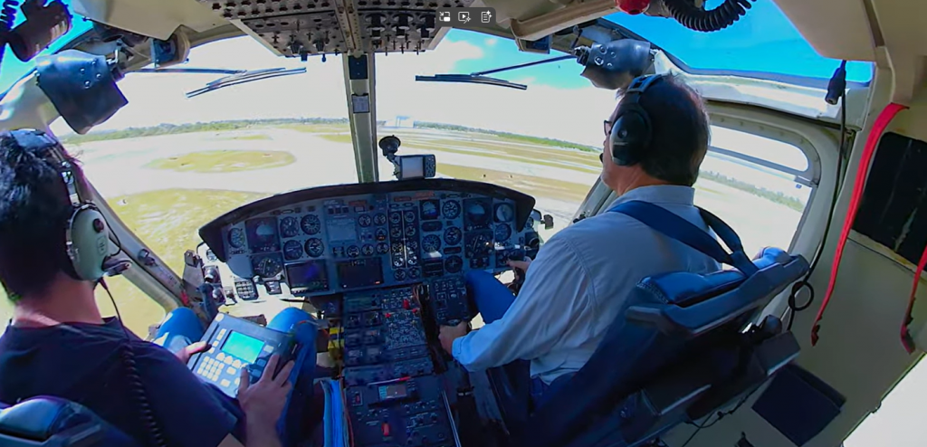
In another example, the pilot of an EC135 in the below video, moves as fast as possible up to each test point with barely a pause in the motion. There is no build up to each test point which could easily catch out the pilot if a control restriction was found. The location used of an operating dispersal also removes any option to allow deviations in the event of identifying control malfunctions. Note how the nose dips during the recovery from rearwards flight.
Counting
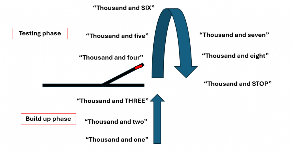
Several typical MCF test points require something to happen over a certain time period (eg a 3 sweep of collective from 20% to 80% torque then back down over 3 seconds). It is not practical for some to time it. It is much better to use a cadence counting technique. Using this technique you begin counting before the test begins to enter a rhythm and atune your brain to how much time they have to do the task. Then the action itself starts on the “three” count and lasts as many counts as required. The words “A thousand and ______” are used to keep the time intervals around one second.
For example, if we needed to do a 3 second sweep up followed by a three second sweep down, the testing would happen between the 3 count and the 9 count. This technique can also be applied to spot turns. If the required rate is 30 degrees per second, a full 360 turn should take 12 seconds and of course you could break that down further so each 90 should be 3 seconds.
Contingencies
Murphy’s law states that what can go wrong will go wrong. As part of the risk management process, the consequences of system failure need to assessed for each manoeuvre.
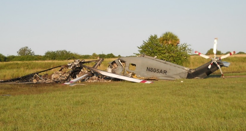
This will be covered in more detail later, but consider the required actions in the event of a power loss during low speed manoeuvres. A landing might be necessary so a nice hard flat surface and a relatively low hover height might be a good idea. However, in an incident on 6 September 2016, a Sea King N805AR was conducting a low speed check as part of maintenance check flight. For some unexplained reason, the crew were carrying out this test at 200 ft above ground level.

Subsequently when they experienced a power loss, they were not in a good position to make a successful landing and the aircraft and crew were lost. A lot of things went wrong that day, but a lower height for the test may have given them an escape.
Tools and Test Equipment
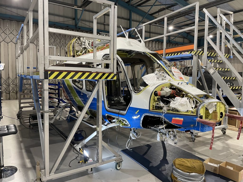
Several MCF requirements require tools to be carried in the cockpit by a task specialist. These can range from a simple ruler for measuring control displacement during a Mast Moment Indicator (MMI) check on an EC135, to sophisticated cameras and computers for track and vibration monitoring. These must be appropriately managed by a task specialist in flight and must be carefully inventoried on entry and exit from the cockpit to ensure no parts are left behind.
As can be seen in the example below from Hope Aero, the computer and camera for track and vibration may be a substantial size and could interfere with controls if not carefully managed. Occasionally temporary wiring on the outside of the helicopter may be needed to connect to sensors (notably the Puma HC Mk2 in RAF service). This must be checked for security.

“Heads In” and who looks at what
By necessity the crew will need to record various bits of data during an MCF. This will require the crew to be heads down in the cockpit reading instruments or operating computers. In addition a lot may be happening at the same time, so several sets of eyes may need to looking at different gauges at the same time. It is important to pre-brief who is going to look at which gauge during a test point, balanced against the need to maintain situational awareness.
One strategy may be to use a camera to capture screens quickly before recording the data in slow time later. This does risk of carrying a Portable Electronic Device (PED) in the cockpit and is prone to error if the right data is not in focus on the display. A quick snapshot may also be really helpful if something abnormal occurs.
In any case, the crew need to communicate effectively during a flight test to ensure they are aware when an individual is looking down. This can include making “Heads Down” and “Heads Up” calls as appropriate
Plan to Fail
As already highlighted, an MCF should planned in the expectation that it will not pass the requirements of the check. So for an autorotation check, it may not ever achieve true autorotation. What is the plan at this point? Probably return to base and abandon the remainder of the test points. What about a failure of the track and balance segment? Can the handling checks still be done? These decisions should ideally be made in the planning stage so the trip procedures smoothly.
It is also worth considering how to recover from an abnormal state if the results are not great. Say a hydraulic system is switched off. In the event of abnormal results, who and how are normal operations going to be resumed. The hydraulic test on a Bell 429 is completed using the HYD 1-OFF, NORM, HYD 2-OFF switch. If the controls jam up during the test point could the task specialist flick it back for the pilot? Could the pilot give a clear explanation of what is required on the fly?
Specific Manoeuvre Guidance
Now we can move onto more specifics. Below are some top tips for each of the following MCF areas.
Checklists and Procedures
As already mentioned, an MCF is time to be methodical and use the normal checklist on start rather than a macho memory test of a long sequence of switches. Have the manufacturer MCF procedure available. As found during the incident on G-EZJK the use of “customised” or local procedures for MCF test points is fraught with danger.
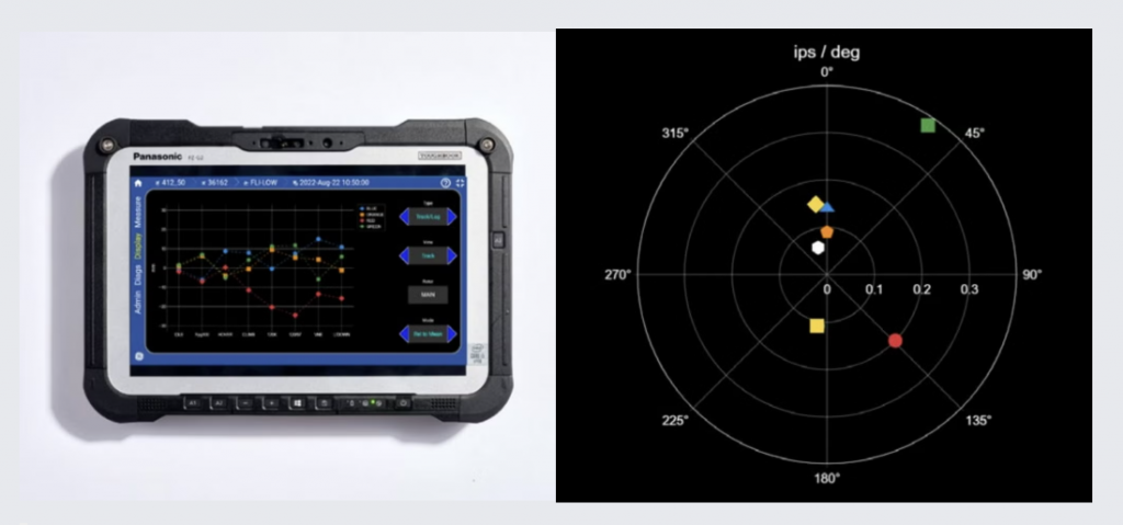
Track and Vibration Testing
Track and vibration testing can appear on the face of it to be quite dull. Achieve and maintain a set speed while the engineer runs their computer program to get data. However, there are some important issues the pilot needs to consider:
- Straight lines – the test equipment needs a period of steady straight flight to gather the data. It normally also needs to be in level flight. Is there enough airspace available? For multiple test points in a row, does the pilot want to turn back towards base after half of the points are completed to achieve the sortie more efficiently? Is the flight path for the next few minutes clear of threats (clouds, traffic etc).
- High speed test points – On some aircraft, one test point is the maximum level flight speed – do not be a hero! Give yourself a margin from the torque limit to allow for error/turbulence.
- Vibrations – We have already covered how to report vibrations in our earlier article – Bad Vibes – How to Report Vibration on Helicopters
Ground Taxy Testing
On wheeled aircraft, there will often be a test of various systems associated with the undercarriage, steering and brakes. This is a great example of where incremental testing is appropriate. A test of brakes straight away from maximum ground taxy speed might reveal you have no brakes! This might require an unplanned take off in less than ideal location. Do a test at low speed first and always be prepared to lift off (eg in the event asymmetric brake application leads to a swerve)
Running landings are a related set of tests. The pilot needs to plan for the brakes either failing to operate (lift and abort) or binding (lift!). Again, incrementally approaching a full speed test point might be prudent. What would happen if one wheel failed to roll freely and pulled the aircraft to one side? Plan for it!
Engine System Testing
Engine systems testing ranges from a simple automated power check to a climb up to 10000 ft to check the N2 datum is set correctly. The test may involve the movement of power select levers or throttles. All of these tests present a risk of exceeding a limit or trashing the engine in extreme cases.
Operating engine controls
When ever engine controls are moved during a test, the “safe” direction of movement must always be instinctive. This might be retarding a throttle to idle. On most helicopters with twist grips the mantra “Thumb down, throttle down works for a throttle held in the left hand.
In one particular EC135 T power system test, the “Preference Injector Check” the throttle needs to manually wound up past neutral to a a very high power setting just below the limit. The throttle is then snapped closed to minimum to check that the engine does not flame out. There have been several incidents where the pilot snapped open the throttle instead and torched the engine. A dry practice with the hand away from the throttle is prudent here. Fortunately Safran have now introduced a new automated procedure that involves selecting a series of unrelated engine switches to make the test happen automatically (like a cheat code on Super Mario).
Adjusting Power Datums in Flight
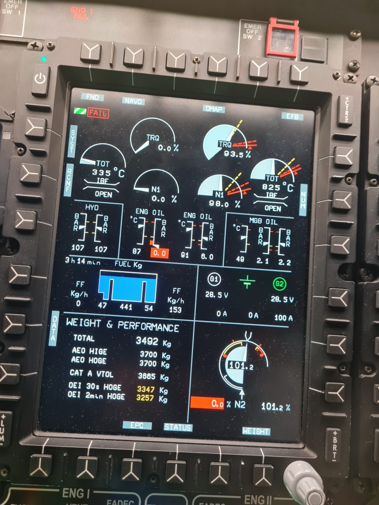
In some aircraft, the fundamental datums of the aircraft (eg the N2 datum setting) have a critical effect on the aircraft operation. If set wrong, the engine can exceed limits during certain flight conditions (eg at high altitude where the air is thin and the engine needs to spin fast to compress enough air). The test can involve climbing to such high altitude and checking what the N2 tops out at.
N2 adjustment
On the EC135, this test on P2/T2 and P2+/T2+ involves a long steady limb to around 10000 ft before the datum is adjusted by an engineer in flight with a screwdriver. The adjuster changes the N2 on both engines on these variants. It operates slightly differently on P&W-engine aircraft vs Turbomeca-engine variants but in basis terms the engineer loosens a locking collar, then uses a screwdriver to adjust a potentiometer to set a new datum.
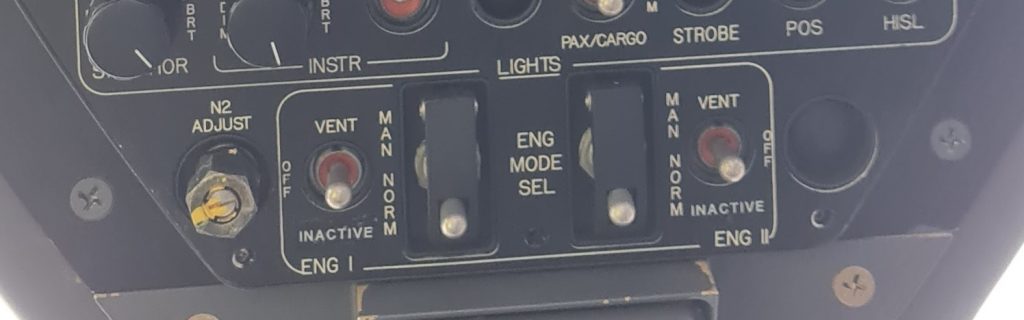
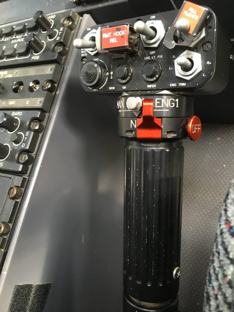
On 5 April 2018 an EC135 P2+, G-POLA, was conducting an MCF including the N2 adjustment climb. When the engineer in the left hand cockpit seat went to adjust the potentiometer it broke and both engines went to the minimum N2 setting (full runaway down). The pilot now had an emergency not described in the Emergency Checklist – a double governor malfunction. He attempted to gain manual control of the engines by rotating the throttles up past neutral. Unfortunately he could not remove the red guard on the throttle which stopped movement of the throttle.
The pilot could not move the guard due to wearing thick gloves due to the altitude. Fortunately the engineer managed to re-adjust the broken potentiometer to stablise the N2 and the aircraft was recovered safely. Lots of recommendations came out of the AAIB report but of most interest is the restriction of future tests to TRI and TRE. Does that mean it has been deemed a Level A check?
Throttle guard origin
Incidentally, the throttle guard was introduced following 2 incidents on EC135 P1 where the pilot inadvertently moved both throttles in flight and oversped both engines (N44NY on 3 December 1998 and N601FH on 30 May 2006). As soon as the throttle is moved away from neutral on a P&W engine EC135, the engine immediately goes into manual. A specific procedure was needed on early PW206 to get it back into automatic mode. Unfortunately an almost identical incident occurred on N312SA on 7 July 2018 as the change to the throttle was not mandatory.
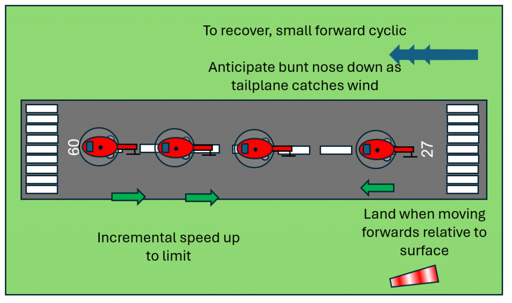
Low Speed Testing
The low speed test phase of an MCF is usually to determine if handling feels normal during sideways and rearwards flight. As already highlighted above, the pilot should plan for failure and should also plan for a critical malfunction during the procedure. Thus an incremental approach with a close and clear landing area is a must.
The test points typically involve increasing up to a given speed or yaw rate to test the aircraft. The speed is a speed through the air. In the event of an emergency landing being required the less groundspeed the better. Therefore, all tests should be conducted into the prevailing wind or at least with some into wind component. Thus with a 15 kt wind, a 30 kt test point only requires a 15 kt groundspeed. This is particularly true for rearwards test points.
Always complete low speed test points into the prevailing wind
Recovery following power loss
In the event of a power loss, the priorities are to land with no lateral drift and at a low as possible groundspeed. For very low rates, either laterally or angular, the aircraft can just be stopped on axis and landed. Once speed is above about 10 kts, the power of weathercocking into the wind should be used to align the aircraft with the direction of travel over the ground. This effect outweighs the potential extra power of using “power pedal” to align the aircraft. This should be practiced in the simulator if possible.
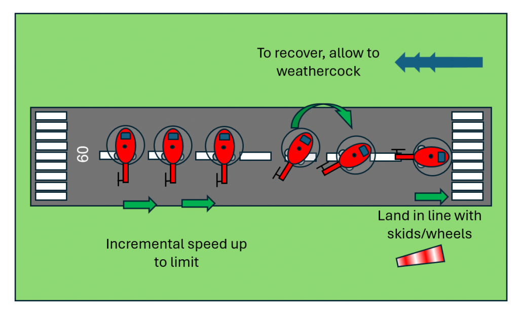
During rearwards flight, stopping the aircraft at any significant speed rearwards will likely result in a dip nose down during the recovery. The aircraft should be allowed to climb slightly to allow a forward run on.
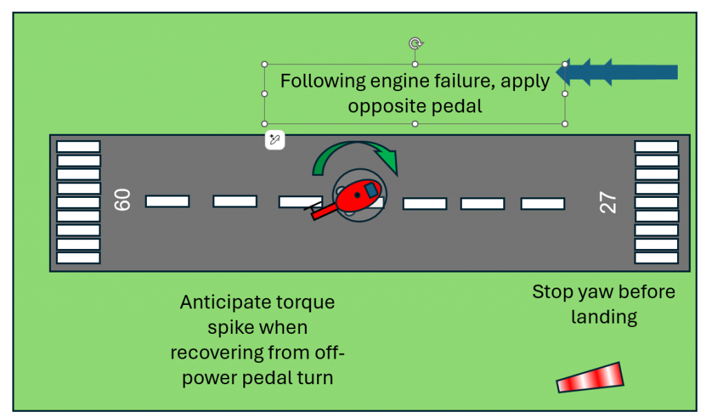
For spot turns, the arresting of a turn may require significant pedal movement (particularly on fenestron equipped aircraft). But remember – fenestron stall does not exist – push and hold up to full pedal as required to stop any yaw. There may be a torque spike if an excessive rate of “power pedal” application is made. Anticipate this when stopping from a right turn in American/Italian/German helicopters
Compass Swings
Compass swings can be quite benign but they can also lead to an airspace infringement or dynamic rollover for the unwary.
Airborne compass swings
Airborne compass swings can require flight in a large loop to align an AHRS system. Positioning at the start of the test sequence should consider where the aircraft will drift down wind during the test.
Ground compass swings
Ground compass swings can involve many repeated landings on to precise headings in 30 degree increments. There can be a lot of perceived pressure to get each landing heading accurate to within 1 degree with a lead to very quick take off and landings. This can lead to either scraping skids on a hard surface or placing high side loads on tyres. In extreme cases, increasing adding yaw pedal before lift could lead to high enough side force for a signficant roll on lift. Slow and steady wins the race here!
High Speed Testing
High speed test points might be part of track and vibration programme or a handling test point. In any case, the test points should be approached carefully, paying attention to the engine limitations and any ancillary speed limitations (eg searchlights, wipers or DV windows).
Planning for power loss should be considered. In these flight conditions a sudden loss of one engine could lead to the remaining engine being very highly stressed. A rapid flare should allow power to be reduced quickly but a turn or climb should also be considered to assist with reducing the speed quickly.
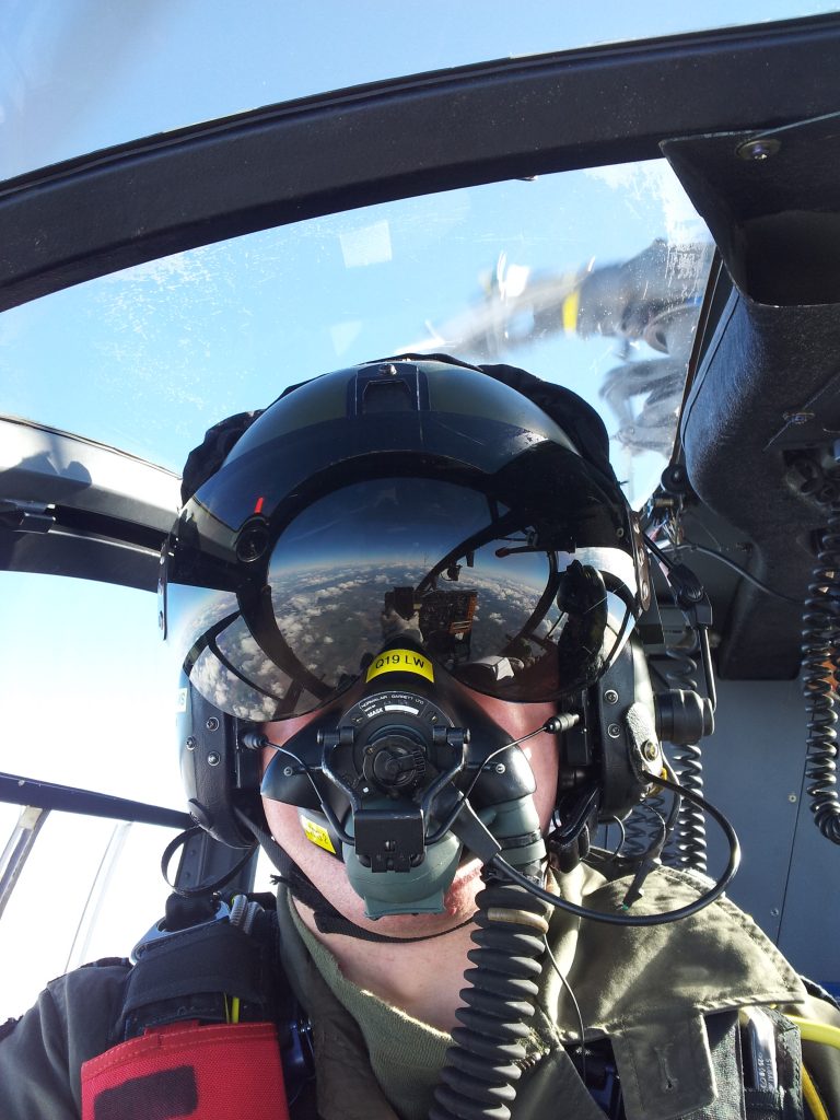
High Altitude Testing
As already covered, high altitude testing should be planned to be clear of controlled airspace which might require a different scale of chart or different settings on an EFB. It may also be quite cold at altitude with 10000 ft (-5 degrees celsius in an ISA atmosphere). Appropriate clothing should be worn but perhaps not thick gloves if it will interfere with normal operation of the controls (see G-POLA incident).
One tricky point to consider is a fire. At 10000 ft an engine or cockpit fire presents a tricky dilema. The time required to descend from 10000 ft is signficant and may give a fire time to cause critical damage (see our article about the incident on N109BC on 28 August 2023) or kill the crew. Whilst flying with a parachute is possible, it is an option only usual available in developmental flight test.
A much more practical solution to getting down fast is to practice a high speed, turning autorotational descent. In this flight condition at maximum autorotational speed with a high bank angle, the rate of descent can be extremely high with only a few minutes required to get down to ground level. This might be the difference between surviving a fire or not!
Autorotations
Now back to more sedate autorotations, the requirements of MCF autorotations can vary significantly between types. As ever, the focus of the pilot should be on what might go wrong.
The first key point is the aircraft might not be able to autorotate! A mistake in the setting of the rotor blade blade pitch or collective rigging may result in an inability to reach the required blade pitch. Or on the flip-side, the tendency of the rotor to exceed the upper limit might be very high. An incremental approach and the ability to quickly return to base in the event of finding you cannot autorotate is sound planning.
For some types, there are some failure wild requirements for the autorotation MCF. On Gazelle for example, a zero speed autorotation test point was required during which the pilot carried out a 90 degree pedal turn to the left to confirm the minimum pedal stop was correctly set. This manoeuvre was outside the normal flight regime (a Level A MCF then!). In practice, it was not that exciting once practice was gained in entering and exiting the manoeuvre but definitely not for a new pilot.
Abnormal and Emergency Systems Testing
Testing of emergency systems can present lots of new hazards. For example, on H125 helicopters, operation of the helicopter with the hydraulic system can lead to a loss of control (see incident on VH-BAA on 7 November 2017). On EC135, testing of the engine training mode, can easily lead to engine damage if the correct sequence of switches is not used (eg if the engine is retarded to IDLE without the training mode being armed). MCF pilots need to ensure they have a sufficient level of practice
Entry to Abnormal / Emergency State
Any condition where the aircraft is intentionally degraded to test a system should require appropriate training. For instructors this may already be in place (eg for manual throttle exercises or hydraulic failure training) but for non-instructor MCF pilots the appropriate entry to an abnormal aircraft state for a test should be carefully trained.
Exit from Abnormal / Emergency State
The exit from an abnormal state should be even more rigorously trained as the correct actions may be needed under significant duress. During the incident on VH-BAA, the system may have required 2 switch selections to restore normal function due to an incorrect setup of the scenario by the instructor. For an MCF, the system should be restorable with minimal effort.
Post Flight Reporting
Phew – the MCF is all complete. Time to go home. Not quite!
On return from an MCF, whether successful or not, it is vital for the results to be communicated to the engineering team in a clear way. Often there is a proforma which is great for reporting numbers and passed test points. It is more difficult to communicate when things are wrong or something does not feel quite right.
The most robust way to debrief an MCF is to talk with the engineering team on return and to follow it up with a written debrief. A paper trail for an intermittent or marginal fault can be really important for traceability in the future and to give the next pilot a fair chance of working out whether a fault has been cleared. Refer to our article on vibration for a methodology for reporting unusual vibrations on helicopters.
Conclusions
MCF can be quite simple and almost dull for a straight forward track and vibration run but hidden faults and system failures at awkward points in the test can raise the pilots heart rate and provide some challenging flying. Hopefully these points are useful for pilots new to MCF and those who have been at it for some time.
Take a look at our earlier articles.
- Keeping up with the Norwegians – Six amazing innovations for UK HEMS
- LNAV/VNAV (SBAS) – Are they approved for use in the UK?
- Helicopter 2D IFR approaches – Is CDFA the best choice?

- Understanding Helicopter Flight Manuals – Everything you need to operate safely

- Post Maintenance Flight Tests – How to avoid fatal traps

- First Limit Indicators in Helicopters – Deadly mistakes to avoid
- Bad Vibes – How to report vibrations on helicopters
- Autopilots, cross-checks and low G in helicopter unusual attitude recovery

- Expert site surveys – Improving the assessment of onshore landing areas
- Lights, helipad, action! The problem with new helicopter pad lights
Leave a Reply