
Designing hospital helipads so they are safe and efficient is a fine art. A growing body of guidance is provided by the aviation authorities to help with delivering effective capability from day. However, some of the guidance is currently flawed; there is an assumption that bigger helicopters are the most restrictive when actually it’s what is behind you that also needs to be considered carefully.

Contents
Background
When operating helicopters to helipads in commercial operations, the obstacle environment needs to be carefully assessed to ensure the helicopter will not collide with anything during the arrival or departure, even if one of the engines fails. The way this is regulated under the UK CAA/EASA is through Performance Classes – see CAT.POL.H.100 onwards.
In Helicopter Emergency Medical Service (HEMS) and Air Ambulance operations, helicopters frequently need to land at hospitals to load and unload patients. This can be in single or multi-engine helicopters but in the UK all HEMS and Air Ambulance helicopters are twins. Generally the Performance Class rules specify that approaches to these hospital pads need to be done under Performance Class 1, in particular for sites in congested and/or hostile areas including elevated helipads (there are a few exceptions of course).

Design Standards for Helipads
Helpfully, the CAA have published CAP 1264 – Standards for Helicopter Landing Areas at Hospitals to assist hospitals with designing hospital helipads to cater for these helicopters. This is now in its 3rd edition, with the latest addition being guidance on Operations Manuals for the hospital helipads which is great progress. The strong recommendation where possible is for the helipads to be elevated and directly linked to the Emergency Department which is sadly not the case for many legacy landing sites – but we can dream.
CAP 1264 provides a comprehensive guide for selecting the right helipad type and providing an adequate area free of obstacles so helicopters can operate in Performance Class 1. But with multiple different helicopter types operating in each landing sites user area, the designer of a helipad is directed in paragraph 2.4 of CAP 1264 to select “…the most critical type…”. Great advice.
The Design Helicopter
However, later in paragraph 3.24 it states “…the most critical type in respect of the dimensional design aspects…”. Perfect, nice clear advice. The BIGGEST helicopter is therefore the most critical type. The CAA have not just made this guidance up. It is derived from ICAO Annex 14 Volume II (the Swiss helpfully provide a great set of links here) which is even more definitive stating at the very beginning of Chapter 1:
When designing a heliport, the critical design helicopter, having the largest set of dimensions and the greatest maximum take-off mass (MTOM) the heliport is intended to serve, would need to be considered.
The largest helicopter for UK HEMS/Air Ambulance is currently the AW169. This has a largest dimension (D-value) of 14.65m. This should then drive all other considerations (of course UK SAR helicopters are bigger and may need to be considered if not using a secondary site). Job done.

A flawed approach?
However, it is crucial that the guidance is updated in ICAO Annex 14 and CAP1264 to also consider another factor – obstacles in the back up area. It is covered but it is not stressed how it may be the most limiting feature and how the biggest helicopter is not necessarily the most restrictive in this aspect. Let’s dig further.
Each helicopter which can operate in Performance Class 1 is certified to Category A which includes provision of a landing and take-off profile for landing on a helipad (either on the ground or elevated). I will not try and explain these manoeuvres here – there’s plenty of description elsewhere. In all cases for UK HEMS/Air Ambulance, there is profile for use at helipads which involves a rearwards or sidewards take off keeping the helipad in sight. Whilst some helicopters now have pure vertical profiles, these usually do not have much scope to be varied to account for obstacles in the departure path or require specific upgrades so I will not cover these vertical profiles here.
Performance comparison
Each of these rearwards/sidewards profiles has an assumed angle which provides predictability of how far behind the take off point the helicopter will be at a certain height. These are shown for comparison below. Note the vertical scale is not quite exactly the same scale as the horizontal scale – it is expanded slightly for clarity (the AW109SPs profile is the same as for AW109S).

The first takeaway is that there is not much correlation between age or mass of the helicopter and the steepness of the profile. The other point to note, is that the biggest HEMS/Air Ambulance helicopter, the AW169 is also blessed with a steep approach and departure (some say its not a blessing when trying to fly this at night!). The AW139 is not used for HEMS/Air Ambulance but is an interesting comparison being remarkably shallow – perhaps another result of the AW139s high nose up attitude in the hover!
Obstacle clearance around Helipads
However, the profile itself does not directly correlate to the maximum permitted height for obstacles in this back-up area (or under the approach path). The typical presentation of this data is shown in Appendix C of CAP 1264 and are originally sourced from the operational regulations guidance material in UK CAA/EASA and ultimately ICAO. No obstacles are permitted in the back-up area above the red line. The backup profile is fairly unique in the performance realm as it is entirely unaffected by the mass of the helicopter during a particular approach, the pressure altitude, temperature or wind.


The MD902 profile is the shallowest of all the profiles and would logically therefore the most limiting obstacle environment under the departure/approach path. However, there are few of the type left in the UK and the manufacturer does not provide the data so I will exclude it.
The other helicopter’s profiles are shown below, along with colour-matching shaded areas showing their published areas where obstacles can be present in the backup area. No obstacle criteria is published for AS365 N3 but it is unlikely to be limiting being so steep.

The Combined Design Helicopter
Hopefully this is not too confusing! To interpret this diagram, the most limiting permitted obstacle area is the lowest for any given distance behind the take off point. If you look at it carefully you should note the AW169 is not the most restrictive!
You might reasonably say the EC135 T2/T2+ profile is the most restrictive but look at the lower part of the A109S/SP – this requires no obstacles to be present 40 metres behind the take off point. Excluding the A109S/SP brings the obstacle free area behind the take-off point to 22.3m for the Bell 429.

The most restrictive aircraft is actually a combination of the AW109S and the EC135 T2/T2+. However, they are undeniably smaller than an AW169 so which helicopter should a hospital helipad designer choose as their “Design Helicopter” as described in CAP 1264? The answer is not to choose one helicopter at all. CAP 1264 is wrong in the following statement:

Frustratingly, CAP 1264 is inconsistent. Elsewhere, it does mention considering the performance of various helicopters as a factor in choosing a design helicopter.
Most limiting parameters
The designer should actually choose the most limiting helicopter in each of these categories:
- Weight – AW169 (or likely SAR helicopter)
- Size – AW169 (or likely SAR helicopter)
- Backup obstacle criteria – A combination of AW109S and EC135 T2/T2+
These will of course vary if a particular type may never land at a particular site but the methodology is the same – the AW169 is unlikely to be the most restrictive in the backup area. As CAP 1264 suggests a detailed consideration of the Flight Manuals of each likely type needs to be considered when choosing that Design Helicopter – I would suggest the back-up obstacles need to be given particular focus! If you are a stakeholder involved in a hospital helipad project, make sure Flight Manual supplements are readily available, along with expert interpretation.
Obstacle Limitation Surfaces
However, is the solution in CAP 1264 after all? What about the defined obstacle clearance slopes that have to be defined. For Performance Class 1, the obstacle clearance slopes along the defined approach and departure paths need to be as follows (Design Category A is Performance Class 1):
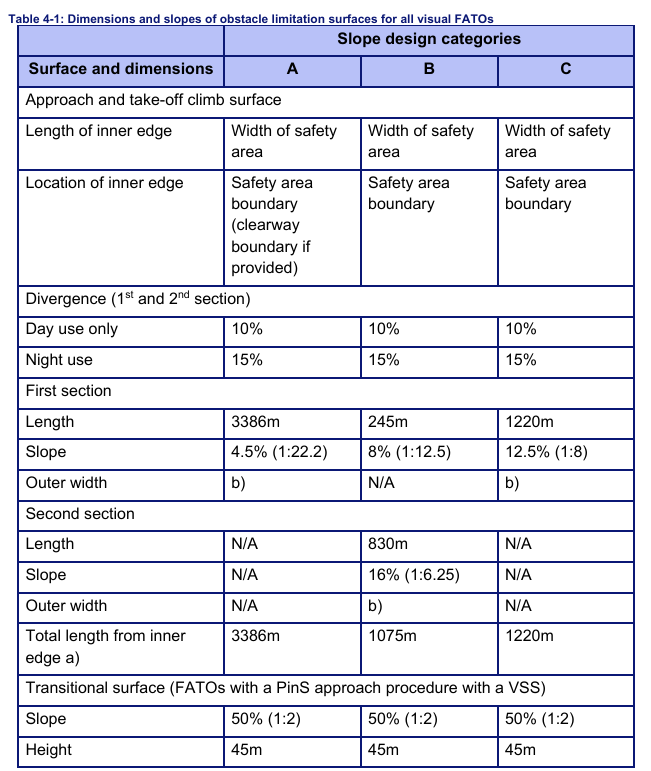
Let’s overlay that obstacle surface on our backup diagram for comparison (using the AW169 as an example for the defined edge of the safety area):
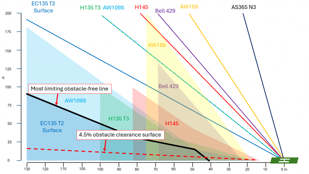
It is immediately obvious that the 4.5% slope is very conservative. Should all obstacles above that surface be removed, you would have an easy time in also all helicopters. However, a couple of other points drop out of this:
- There is a significant area from 0 to 40 m behind the pad where obstacles permitted by the 4.5% would preclude AW109 operations.
- That obstacle clearance surface is very unrealistic at many hospitals in the UK. An average tree (about 30 ft) would have to be over 200m away from the pad in the approach and landing direction. There will be obstacles above that line that are significant enough to not be disregarded in accordance with para 3.35. The 4.5% slope can be raised above the landing site but it would impact the profiles highlighted above:
Thus, this potential reprieve for CAP 1264 falls flat.
Conclusion
I look forward to seeing CAP 1264 developing further and overcoming the error born in ICAO Annex 14. It looks like an indispensable tool in onshore heliport design with a little flawed as it stands.
Check out my other posts:
- Keeping up with the Norwegians – Six amazing innovations for UK HEMS
- LNAV/VNAV (SBAS) – Are they approved for use in the UK?
- Helicopter 2D IFR approaches – Is CDFA the best choice?

- Understanding Helicopter Flight Manuals – Everything you need to operate safely

- Post Maintenance Flight Tests – How to avoid fatal traps

- First Limit Indicators in Helicopters – Deadly mistakes to avoid
- Bad Vibes – How to report vibrations on helicopters
- Autopilots, cross-checks and low G in helicopter unusual attitude recovery
- Expert site surveys – Improving the assessment of onshore landing areas
- Lights, helipad, action! The problem with new helicopter pad lights
- Helicopter on Fire – Could accident investigators have learned more?
- The Ultimate Medical Helicopter – Selecting the right machine for HEMS
- Deconfliction in HEMS operations – Practical methods for keeping apart
- HEMS Landing Sites – Reliable places to drop your medics
- Planning to fail – The perils of ignoring your own advice
- 2D or not 2D – How much room do I need to land a helicopter?
- What is your left hand doing? How to use a 3-axis autopilot on helicopters

- My tail rotor pitches when it flaps! Why?
- Practical ILS explanation for pilots – the surprising way they really work

- Slow Down IFR! Are you speeding on the ILS?

Leave a Reply