
Helicopter pilots have several options for how to fly a 2D approach operation such as an LNAV, VOR or NDB. The fixed wing world have standardised on using Continuous Descent Final Approach (CDFA) as their method of choice. Is it time for the helicopter world to follow suit? Recent changes in how the approach can be flown in the UK and Europe may have further stacked the scales in favour of CDFA – you can skip ahead to this bit if you can’t wait!

In this article, we explore the 3 options currently available to helicopter crews for flying a 2D approach operation and look at the relative merits – Pilots Who Ask Why have also looked into this but we build on their work and now need to dig deeper.
In this article there is a particular focus on the acceptance by the UK CAA and EASA that for a CDFA an MDA/MDH can be treated as a DA/DH without modification or increment. This change applies as equally to fixed wing pilots as it does to rotary wing pilots so there is much to learn for both camps.
Note, this article is strictly aimed at the UK CAA and EASA regulations. The US FAA have a different view and some of the conclusions reached in this article do not apply to the FAA…yet. Interestingly the FAA view aligns with the ICAO SARPS but UK CAA and EASA do not. Let’s dig a big deeper.
Contents
3D vs 2D Approach Operations
In terms of IFR approaches there are several ways you can break down the types of approaches into groups: Type A vs Type B, Precision vs Non-Precision or 2D vs 3D. Each has its merits and each is still in use today in various contexts. The UK CAA and EASA have firmly moved onto the latter for how an approach is flown in terms of the Air Operations Regulation. In the Definitions section it states:
(69d) ‘instrument approach operation’ means an approach and landing using instruments for navigation guidance based on an Instrument Approach Procedure and is either:
(a) a two-dimensional (2D) instrument approach operation, using lateral navigation guidance only; or
(b) a three-dimensional (3D) instrument approach operation, using both lateral and vertical navigation guidance;
Notice the “operation” at the end? It is all about how its flown not what sort of approach technology it is. Very similar to the split between Category A (the what) and Performance Class 1 (the how) of helicopter take off and landings (dive back into one of our earliest articles for more about that confusion.
3D Approach Operations
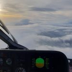
An example of a 3D approach operation is an Instrument Landing System (ILS). Take a look at our article to see how they really work – Practical ILS explanation for pilots – the surprising way they really work. The pilot follows lateral and vertical guidance to follow a defined flightpath to a point where visual references can be obtained. Note very carefully here that the approach and runway lights are optimised for an aircraft coming out of the cloud on the glidepath at a suitable range…we will come back to that!
Another example of a 3D approach operation is Localizer Performance with Vertical Guidance, more commonly known as an LPV. Widespread across Europe, they are currently not available in the UK due to a questionable discretionary decision made during Brexit – there are moves to reverse that decision – see AOPA and Aviation-APPG.
LNAV+V
There is one outlier in the 3D group – the LNAV+V. This is GNSS-based approach with advisory vertical guidance (this cannot be coupled to an autopilot). The UK CAA and EASA regulations are clear than such an approach can be considered as a 3D approach operation for the purposes of flying technique and currency/checking. This is only to LNAV minima and not to be confused with an LNAV/VNAV:
A non-precision approach (NPA) procedure flown as CDFA with vertical path guidance calculated by on-board equipment is considered to be a 3D instrument approach operation. – Air Operations Regulation
Incidentally this is a direct lift from ICAO PANS OPS Volume I, a document we will meet in a minute.
2D Approach Operations
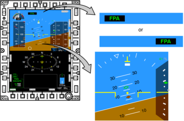
2D approach operations lack the vertical guidance of 3D approach operations. They are inherently less spatially accurate and thus have higher minima. They require more mental effort from the pilot as the vertical profile must be managed directly by the pilot. This is not to say the vertical path is flown manually as some aircraft, notably those with Helionix, can couple the autopilot to a set Flight Path Angle (FPA). This makes 2D approach operations easier but nevertheless they remain less accurate than 3D approach operations.
There are several types of non-precision approaches which can be flow as a 2D approach operation including:
- LNAV – lateral guidance based on GNSS with associated waypoints for distance assessment.
- NDB – lateral guidance based on a Non Directional Beacon (NDB) with either a DME for distance or timing. Very much an “area weapon” on some helicopters!
- VOR – quite rare in some parts of the UK but again distance either by DME or timing
- LOC – just the lateral part of an ILS, usually paired with a DME for distance
No matter which 2D approach operation we are talking about, how the approach is flown has a dramatic effect on the pilot workload, likelihood of achieving visual references and utility of the autopilot in achieving the approach.
2D Approach Operation Methods
It would be slightly crazy for each country to design instrument approaches using a local method without co-ordination across the globe. Through ICAO, a standardised set of Standards and Recommended Practices (SARPS) are applied to instrument approach procedure design. These SARPS are contained in the annexes to Chicago Convention plus some ICAO “Docs”. The Swiss helpful provide access to these free of charge. Take a look at their website here – BAZL – Annexes to the Chicago Convention.
The SARPS associated with instrument design are called PANS OPS. Volume I lays out the 3 options for flying a 2D approach operation. We will cover each in turn before digger deeper into the recent changes made in the UK and Europe to improve the utility of the CDFA technique. Incidentally military approaches (eg TACAN) are also based on PAN OPS but with a military add-on in the form of NATO AATCP-1 – sadly there is not a public link to this document as it is NATO UNCLASSIFIED.
The 3 techniques are:
- Step down descent (“Dive and drive”)
- Constant Angle Descent
- Continuous Descent Final Approach (CDFA)
Let’s dig in!
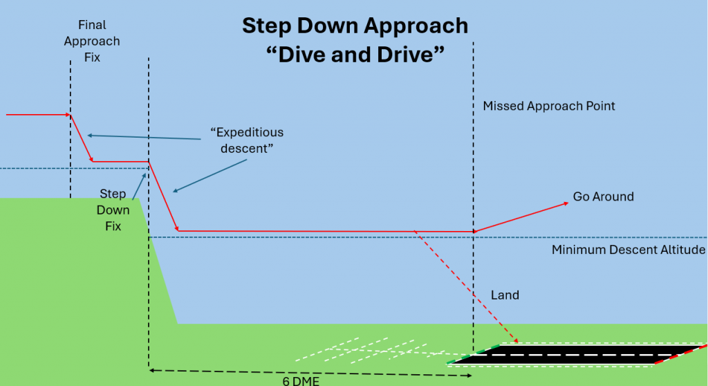
Step down descent (“Dive and drive”)
This is undoubtedly the most extreme way to achieve a 2D approach operation. It involves an “expeditious descent” where the pilot “descends immediately” to not below any Step-Down Fixes or MDA as appropriate. The level flight is continued until visual references are obtained or the missed approach point is reached.
This technique can lead to getting through a cloud layer as fast as possible but involves a very high workload and large changes in power settings and trim. The long level flight portion whilst hunting for visual references can also be challenging at low altitude with limited references.
A step down descent might be seen as the least worst option in some emergency circumstances to try and get visual references (eg an uncontained fire) but is unlikely to be a “default” option. There can also be problems with seeing the “wrong” references in the undershoot of the runway due to the long run in. See the incident report of G-FLTM which tried to land on a tower block’s lights when the pilot looked up too early:
The PF, contrary to the Company SOP, looked out early for visual reference, and saw almost straight ahead what appeared to be the approach lightning of RWY 34. – AAIU Serious Incident Report
Incidentally, the angle of descent is also not without limits. In PANS OPS Volume I it states that the angle of descent using this method must never exceed 15%. At 100 kts groundspeed, that’s 1519 fpm.
Constant angle descent
The second method is the constant angle method. This was the primary method taught before CDFA was invented. The constant angle method involves following a notional glide path (usually 3 degrees) from the Final Approach Fix to reference datum 50 ft above the runway threshold.
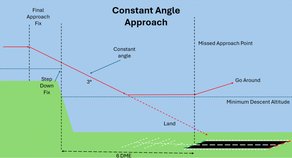
When the aircraft approaches MDA, a decision is made on whether to continue using the constant angle if visual references are available or to level off just above MDA. The aircraft continues just above MDA until either visual references are obtained or the aircraft reaches the Missed Approach Point where a go around is initiated.
From the diagram, the descent is simpler to execute as it is just one angle (very easy with the Helionix FPA mode!). The level off phase is shorter but the aircraft gets really “close” to the runway to give the maximum chance of getting references.
This type of approach is pretty useful for PINS approaches with a “Continue VFR” instruction where the cloud is not as likely to be close to limiting numbers. It gets you visual earlier and there are unlikely to be approach lights to confuse the arguments!
Let’s look at the last option, the CDFA.
Continuous Descent Final Approach (CDFA)
The CDFA concept builds on the constant angle approach to try to improve the safety of approaches.
Stabilized Approach
The concept of a “stabilized approach” is a key building block of the CDFA concept. This is defined in the Air Operations Regulation at AMC1 CAT.OP.MPA.115(a) as:
- An aeroplane should be considered stabilised for landing when the following conditions are met
- the aeroplane is tracking within an acceptable tolerance of the required lateral path;
- the aeroplane is tracking within an acceptable tolerance of the required vertical path;
- the vertical speed of the aeroplane is within an acceptable tolerance of the required rate of descent;
- the airspeed of the aeroplane is within an acceptable tolerance of the intended landing speed;
- the aeroplane is in the correct configuration for landing, unless operating procedures require a final configuration change for performance reasons after visual reference is acquired;
- the thrust/power and trim settings are appropriate; and
- landing checklist completed.
This is not to say that you can only do a stabilized approach using CDFA – you can of course have a stabilized visual approach too. However, what the stabilized approach concept does mean is that we want to minimize changes of configuration and approach path. However, the constant angle approach still involves a last minute configuration/power change. How can we eliminate it?
Bringing the best of 3D approach operations to a 2D approach operation
We do not need to reinvent the wheel. We simply need to borrow the “bottom” of a 3D approach operation. A constant descent profile concluding with a decision: either continue to land or immediately initiate a go-around. For CDFA the descent path can be flown using:
- Manually calculated descent rate based on ground speed
- Manually calculated descent rate based on published approach path
- A descent path coded into the FMS procedure
- An electronically calculated and displayed approach path (but remember this is a 3D approach!)
Fundamentally: You DO NOT need an electronic glidepath to fly CDFA
However, we still have an MDA for our 2D approach operation which we are not permitted to descend below without visual references; it says so in PANS OPS Volume I:

How do we stop ourselves descending below the MDA? Again, PANS OPS Volume I has the answer:
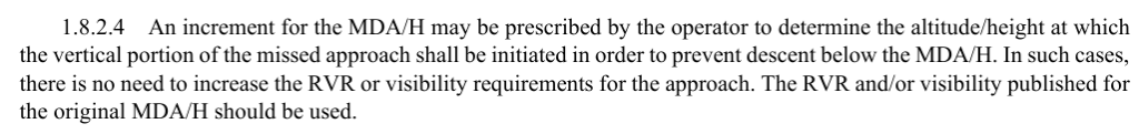
So we add an increment on MDA to create a pseudo DA by which we need to have made a decision and initiated a go-around. What does that look like?
ICAO CDFA
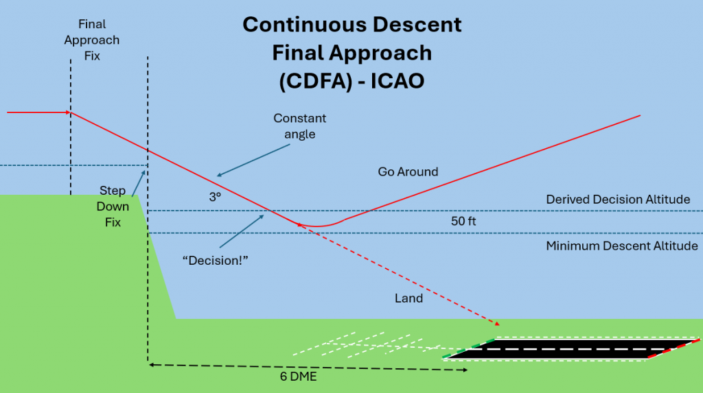
As can be seen from the diagram above, with the PAN OPS CDFA procedure, the pilot makes the decision at a Derived Decision Altitude (DDA). This is above MDA by a increment selected by the operator to ensure the aircraft does not drop below MDA during the go-around manoeuvre. This increment puts the aircraft higher and further away from the runway than is possible for both the constant angle and step down approach methods. However, the stabilized approach concept is all there and it is far easier to automate – take a look at our article about using a 3-axis autopilot for these approaches.
Comparing 2D Methods
Now we have had a look at the various options, let’s perform a comparison. The regulations at GM1 CAT.OP.MPA.115 list the following advantages for CDFA:
- The advantages of CDFA are as follows:
- the technique enhances safe approach operations by the utilisation of standard operating practices;
- the technique is similar to that used when flying an ILS approach, including when executing the missed approach and the associated missed approach procedure manoeuvre;
- the aeroplane attitude may enable better acquisition of visual cues;
- the technique may reduce pilot workload;
- the approach profile is fuel-efficient;
- the approach profile affords reduced noise levels;
- the technique affords procedural integration with 3D approach operations; and
- when used and the approach is flown in a stabilised manner, CDFA is the safest approach technique for all instrument approach operations using NPA procedures.
2D approach operation comparison table
That’s a basis for a comparison, so let’s table it up:
| Approach method | Advantages | Disadvantages |
| Step Down | – Quick descent – Long time to decide – Get close to runway | – Lots of power changes – Inefficient for fuel – Noisy – Complicated to automate – Challenge to fly level – Visual cues below pilots vision |
| Constant Angle | – Easy to fly than step down – Stabilized for most of approach – May be useful for PINS approaches where it is “Continue VFR” | – Inefficient and noisy – Not stabilized due to level phase – Transition to level flight can be challenging – Visual cues below pilots vision |
| CDFA – ICAO | – Identical technique to ILS – Fuel efficient – Quieter – Low workload – Visual cues in ideal position | – Decision is made high and far from runway (“less capable”) – May not work in certain scenarios |
I think it is far to say that crew room discussions amongst pilots on this topic can get quite heated. There are some firm believers in the Constant Angle technique as they want to get closer and lower to better see the required visual references. This is an interesting perspective as perspective is actually crucial. The Missed Approach Point for typical LNAV is the runway threshold.
The view at DA/MDA
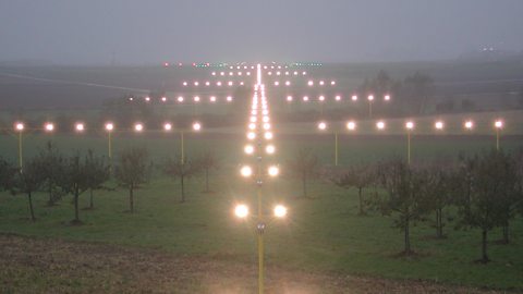
Let’s compare the view. For an ILS, the “picture” at DA might be something like this – a nice set of very bright approach lights laid out specifically to catch your eye at this exact position in space:
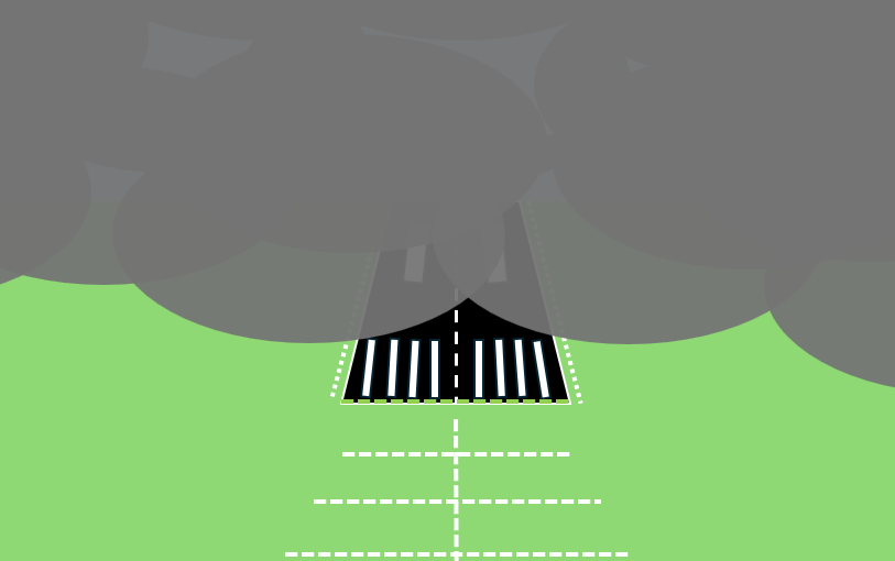
Now compare that to the view at the MAPt for an LNAV which will by definition also be higher than an ILS:

The only remaining lights are the edge lights. The threshold and approach lights are now behind and below you. But you might have seen them earlier if you squeezed really close down to MDA which is a very high workload task!
So on balance, the conversation in the crew room usually comes down to helicopter pilots still wanting to do a constant angle as they are “more likely to get in”. More than one helicopter pilot has however demonstrated that maintaining level flight at low level with limited references is really hard. Is there another way?
Descending below MDA on CDFA
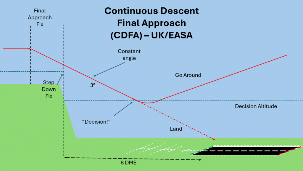
Following at least 2 studies, EASA and the UK CAA determined there was a better way to do CDFA. They looked in detail about how aircraft behave during a go-around and how much altitude was lost during the manoeuvre. They then looked at how obstacle clearance was determined for 2D approach operations and concluded that pilots can safely descend below MDA while executing a go-around. Another way to say this is:
“…a published MDA may be used as a DA for a 2D operation flown using the CDFA technique.” – GM5 CAT.OP.MPA.1101
Shifting the balance – CDFA for the win
This changes the whole discussion. If you do not need to add an increment to MDA and you can descend below MDA during the go-around, CDFA becomes much more attractive. We have an approach that is easy to fly, gets us as low as possible and presents the most ideal view of the approach lights at the right time.
This is in contravention of PANS OPS guidance but the UK CAA and EASA are firm in their regulations. The regulations actually got updated some time ago to allow this. The GM5 above was only published recently to make it crystal clear that it was allowed. Take a look at AMC3 CAT.OP.MPA.110. For some time this has said:
“The decision altitude (DA) to be used for a non-precision approach (NPA) flown with the continuous descent final approach (CDFA) technique…”2
This is not without caveats. Each operator needs to ensure their crews are adequately trained in CDFA techniques to ensure height loss during the go-around is minimised – see GM5 CAT.OP.MPA.110. But of course this minimum height loss technique is normal for a 3D approach so the training burden is not high. But is it really now an obvious choice?
What about using an AFCS?
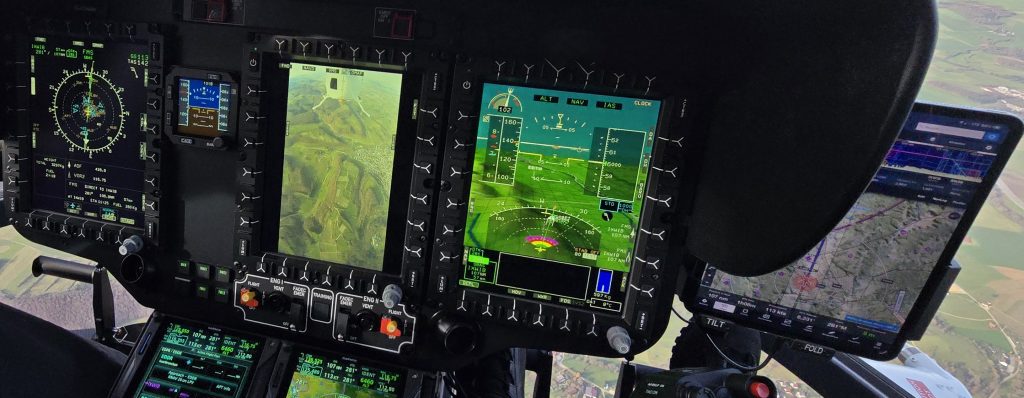
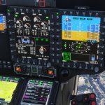
OK, that’s great, but a good Automatic Flight Control System (AFCS), which is well understood by the crew can flip the argument on its head. Let’s go back to the AFCS we already met on Helionix. This AFCS, as fitted to H135, H145, H160 and H175 is hugely capable – the recent Helionix V10/V11 update has added fully automated Category A take offs for example. But with respect to our 2D approaches what does a good 4-axis autopilot offer in this domain?
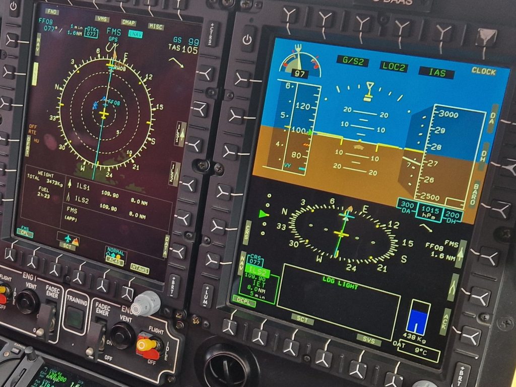
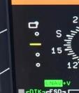
Let us consider a 2D approach operation without any vertical guidance. As already mentioned above, the Helionix AFCS can capture and fly a Flight Path Angle (FPA). So capturing the notional glideslope is easy (the system also pre-sets the FPA for the programmed LNAV approach). Now for the part at MDA.
It is really easy to setup an Altitude Acquire (ALT.A) for the level flight phase at MDA to the Missed Approach Point. The workload for the crew is very low, with a lot of opportunity to lookout without compromising the accurate flight control. In this case, many of the issues with the constant angle approach fall away. CDFA with no increment does not seem as attractive any more.
However, with a 3-axis AFCS, particularly a badly implemented one, may give the crew a huge workload at a critical phase of flight. See our article on 3-axis autopilots for more – What is your left hand doing? How to fly a 3-axis autopilot on helicopters.
With this in mind each operator should reassess what is right for their operation. Which can generate a problem…
Checking and Testing of 2D Approaches
There are now effectively 4 options for a 2D approach:
- Step down (Dive and Drive)
- Constant Angle
- CDFA – ICAO – add increment – use DDA
- CDFA – EASA/UK – no increment – use MDA as DA
For operational use, company SOP should make it clear which method is being used. But what about check sorties and tests. Frequently, contractor TRE are used and they may not be 100% versed in company SOP. It is vital for the TRE to ask which method is going to be used if the crew do not specifically brief it themselves. At MDA or in the debrief is not the time to be arguing what is right and wrong.
TRE
Ask how 2D approaches are going to be flown in the brief!!!
Candidates
Brief how you are going to fly 2D approaches so TRE do not have to ask!!
Conclusion
In the UK and EASA, the balance of the argument about 2D approach operation technique has shifted. CDFA without an increment offer a safe method of approach with minimal downsides.
But does a decent, well-managed 4-axis AFCS mean that the constant angle approach lives on for helicopters? There will also be certain circumstances where a manually flown constant angle or even a dive and drive are the right choice but these are likely to be by exception going forward.
What is right for your operation?
FAA Differences
Just a quick note on the FAA differences. For one, the definition of Decision Altitude is actually different. In the UK/EASA it is the altitude at which a go-around must be intiated if visual references are not obtained (see ANNEX 1 to Air Operations – 35a). In the FAA it is the altitude at which the decision must be made (see FAA Glossary).
In addition, in the FAA world you must still add an increment for CDFA to create a DDA (see AC-120-108)
Now take a look at our other articles:
- Engine Failure Training Mode – A safety tool that will punish the unwary
- Automated take offs – Pointless or are they the new standard?
- Keeping up with the Norwegians – Six amazing innovations for UK HEMS
- LNAV/VNAV (SBAS) – Are they approved for use in the UK?
- Helicopter 2D IFR approaches – Is CDFA the best choice?

- Understanding Helicopter Flight Manuals – Everything you need to operate safely

- Post Maintenance Flight Tests – How to avoid fatal traps

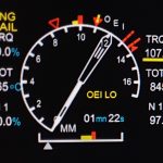
- First Limit Indicators in Helicopters – Deadly mistakes to avoid
- Bad Vibes – How to report vibrations on helicopters
- Autopilots, cross-checks and low G in helicopter unusual attitude recovery
- Expert site surveys – Improving the assessment of onshore landing areas

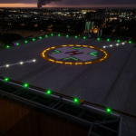
- Lights, helipad, action! The problem with new helicopter pad lights
- Helicopter on Fire – Could accident investigators have learned more?
- The Ultimate Medical Helicopter – Selecting the right machine for HEMS
- Deconfliction in HEMS operations – Practical methods for keeping apart
- HEMS Landing Sites – Reliable places to drop your medics

- Planning to fail – The perils of ignoring your own advice
- 2D or not 2D – How much room do I need to land a helicopter?

- What is your left hand doing? How to use a 3-axis autopilot on helicopters

- My tail rotor pitches when it flaps! Why?
Leave a Reply