

Introduction
Following a few recent accidents with aeromedical helicopters, I thought it is time to take a look at what makes a good landing site for a helicopter. I am going to focus on helicopters being used for aeromedical evacuation (in Europe called “Helicopter Emergency Medical Service – HEMS”) as that is the most likely scenario for landing in peculiar places in the civilian world. EASA has recently provided rules for manned eVTOL HEMS – called VEMS but we are not going to consider that here just yet. However, many of the lessons are valid in other environments.

Contents
Regulations
In UK and European HEMS, crews are not allowed to just land in any size of landing site; there are some rules to follow. These rules are intended to minimise risk to operating crew, the helicopter and third parties.
UK and EASA HEMS Rules
The hard rule for a HEMS landing site is in SPA.HEMS:
The HEMS operating site must be big enough to provide adequate clearance from all obstructions. For night operations, the site shall be illuminated to enable the site and any obstructions to be identified
SPA.HEMS.125 Performance requirements for HEMS operations
SPA.HEMS.125.(b).(4)
So what does “big enough” and “adequate clearance” mean? That is where the associated Acceptable Means of Compliance (AMC) comes in:
When selecting a HEMS operating site it should have a minimum dimension of at least 2 x D (the largest dimensions of the helicopter when the rotors are turning). For night operations, un-surveyed HEMS operating sites should have dimensions of at least 4 x D in length and 2 x D in width.
AMC1 SPA.HEMS.125.(b).(4).(a)

EASA Regulatory Enhancements
Well, that is rule in the UK at the moment; EASA have moved on. The equivalent AMC now reads:
We will come back to what this means later.
D-value
So now we just need a look in our flight manual for the D value as defined above. Typically the “…largest dimension…” is from the tip of a spinning main rotor in front of the helicopter to the most rearwards extent of the tailboom. Note, this is generally always bigger than the rotor diameter. Here are some D value for typical HEMS aircraft:
- H145 D2 – 13.64m
- EC135 T2 – 12.16m
- Bell 429 – 13.11m
- AW169 – 14.64m
- AS365 – 13.73m
So a day site size ranges from 24.32m up to 29.28m for these helicopters. However, if you play devil’s advocate here, where does the 2D apply? Is it at surface level? What about if there are trees that droop inwards (see recent accident in Luxembourg here on Aviation Safety Network)? What if the ground slopes? What about crops, cars, fences and kerb stones? Is it a 2D x 2D square or is a circular site of 2D diameter acceptable? From this seemingly clear guidance in the AMC, a vigorous crew room discussion can ensue. Normally it is up to operators, through hard won experience, to clarify the definition for their own purposes.
Applying the concept of 2D
The first thing to address is whether 2D is a circle of 2D diameter or a square 2D by 2D. I think the right answer here is to say its 2D in every axis. The smallest shape that meets that requirement is a 2D diameter circle. The aircraft does not necessarily have to be in the centre of the circle but normally the pilot will want to keep roughly centralised. No minimum clearance around the structure of the aircraft is actually specified in regulation.
Clear site
In the example below, it is easy to see the football pitch is well in excess of the minimum 2D site. The ground is flat and the grass is short. It’s comfortably large enough.

Non-frangible obstructions
Let’s go a little smaller. In the next example, its tighter in one axis. There is 2D between the hedge and the swing frame. But look closely. What about the fence just to the right of the swing frame; it is inside the 2D so does this make this site less than 2D?
Let’s consider the hazard this fence presents. It is not going to cause any risk to the aircraft where it is. Being just under 1m high, it also does not present much of a hazard if it were under the rotor disk to the side of the cockpit. How about under the tail? In this case, it could hit the vertical fin on this EC135.
On a helicopter with an exposed tail rotor, objects could cause severe damage to the rotating components. Therefore we need some criteria for determining where such a solid obstacle is acceptable. We will categorise this kind of hard obstacle as “non-frangible (it will not squash down if we land on it). We do not want these objects to be under the fuselage or tail structure.

Lumpy ground and slopes
We also need to think about solid ground. What if where we land is not flat? Can we accept some lumpy ground? In the example below, the ground gently rises to the left of the helicopter. Again it does not cause a hazard to the rotor disc or tail rotor in this case, but it could if the gradient were steeper or the slope was under the tail. There is also a completely separate hazard to personnel entering or leaving a turning rotor disc that the pilot needs to manage and there may be a risk to equipment. In this case, the Trakka turret on the nose could be uncomfortably close to the ground if it sloped up in front of the helicopter.
But from a 2D perspective, this example demonstrates we can accept some terrain height variations under the rotor disk and we can group it with objects as a “non-frangible” hazard.

Frangible obstacles
So far we have looked at “hard” objects and surfaces in our landing area. What about things that squash down like crops or foliage? In general, they do not present much physical hazard to the aircraft. However, if they contact any rotating components or enter an intake they can cause significant damage. Crops and foliage can also hide large rocks or deep furrows which could make landings hazardous
In the image below, the crop is a uniform height, reaching the bottom of the fuselage but nowhere near the fenestron. The only hazard here would be difficultly in judging skid contact on landing and possibly some ingestion of crop into the fresh air intake underneath.

The next example is of a landing in foliage of much more variable depth. The crop is well clear of the main disk but is getting close to the fenestron. This is becoming a limiting factor despite being frangible. We need some limitations on what is and what is not ok to land in to protect the helicopter.

Overhangs
We have now established we can accept some hard and soft obstacles in our landing area but we must keep the rotor clear of any obstacles. Now we need to look up. Helicopters operate in 3D and we must consider the flight path of the helicopter during the landing and take off phase as well as the “parked” dimensions of the site.
In this still image taken from a video on Air Pro News, an H145 at a HEMS scene in Luxembourg is about to lift. The trees to the right of him are drooping such that they are in his flight path as he rises to the hover. The landing site may have been 2D at rotor disk height whilst parked but may not have been as they lifted into a hover. Thus we need some guidance regarding how 2D applies during take off and landing as well as while being parked.

It is also worth considering man made hazards. In a recent Bell 407 incident a helicopter lifted and clipped a hangar door above them. Whilst it is unlikely at a HEMS scene to be outside a hangar, objects such as street signs could offer such a hazard. This is particularly relevant on motorways where signs are higher over the ground and could theoretically allow a helicopter to be parked underneath.

2D Guidance
We have now explored what we actually mean by 2D so some guidance can be formulated:
- There should be no non-frangible obstacles above a set height (eg kerb height or less) under the helicopter fuselage and the surface must be within the sloping ground limits.
- Any terrain undulations under the helicopter should not lead to fuselage contact with the surface.
- Any terrain undulations or obstacles should not affect the ability of the skids or wheels to support the helicopter (eg a kerb at the mid skid point)
- There should be no non-frangible obstacles above a set height (eg 1m) within a nominated area around the fuselage, with particular attention to the area around an exposed tail rotor
- Frangible obstacles may be permitted within the 2D area provided them are below a set height and will not be ingested into an intake or rotor
- The approach and departure paths should provide 2D clearance for the rotors throughout the whole manoeuvre
Judging 2D
Judging whether an area is 2D from the air is an art form. It is a skill acquired from practice and checking, supplemented by some electronic aids and some rules of thumb.
Satellite imagery
The first modern innovation in this sphere is satellite imagery which can be obtained through the humble smart phone or through an Electronic Flight Bag (EFB) solution. Typically, a tool exists that allows rapid measuring of distance with a two-finger stab at the screen. I find the measurement to be accurate provided the image is recent. However, plants grow and the image may miss critical objects; telegraph poles and wires being prime examples. But for validation of a site after landing as part of a learning experience or for rough ball-park figures it is indispensable in modern HEMS.

Rules of thumb
Judging distance from a moving helicopter with the Mk1 eyeball can be hard. However, in the HEMS/Air Ambulance role, we often collaborate with other agencies who provide handy markers in the form of their vehicles.
Ambulances and parking spaces
Take for example an ambulance. The latest Fiat Ducato Maxi ambulances are 6.36m long. Imagine 4 of them nose to tail, you have 2D for an EC135. Add another one and you are 2D for all types. A parking space can also be a great visual guide. In the image below you can see 2 parking spaces end to end is about the rotor diameter. It is important to remember though that D is also always longer that the rotor so looks could be deceiving!

Roads
Keeping with the road marking theme, what about a road? Often a HEMS job will be close to a road or even on it. For a motorway incident, the carriageway is the obvious place to land. We can use the standards document for roads to analyse what we have to work with. Take a normal single carriageway trunk road. The paved surface is 7.3m wide. This is significantly less than 1D so the nearby obstacle environment would have to be favourable to land on here.

Ok, so what about a three lane motorway with a hard shoulder. Plenty of air ambulances land on motorways so it must be 2D! The standard figures from CD 127 (link below) show a 3 lane motorway with hard shoulder is 14.3m wide – so nearly 1D for all typical HEMS helicopters. Thus, when HEMS aircraft land or take off on motorways, both carriageways need to be closed. A moving vehicle, particularly a lorry is very unlikely to be acceptable inside the 2D area! But again, a good rule of thumb is that each side of the motorway hard top is 1D. This allows better judgement of whether sufficient space exists between roadside furniture along the road.

We can see from the photo below, that a carriageway is indeed about 1D but that there is a lot of road furniture that is inside the 2D. Banked edges, lamposts, wires and bridges can restrict where a suitable 2D site can be found. Shutting both carriageways also takes time.

Don’t be fooled!
Using items of known size can be really helpful in judging the dimensions of a site from the air. A football pitch is 100m long for example. However, it only takes a simple dislocation of expectation for you to be disappointed. The tiny goal posts and sub-sized pitch did not catch out the crew by day in the example below but could have led to an unfortunate optical illusion through NVIS.

Being judged on 2D
Flying an air ambulance or HEMS aircraft is very definitely a spectator sport. You will get photographed at most scenes so your judgement of 2D as a crew can be assessed by others from an arm chair. Despite careful work, using every scrap of skill you have, a solidly 2D+ site can be shrunk by the lens to catastrophically small proportions.
Lets take an example. In the photograph below, the proximity of a whole myriad of obstacles and hazards seems to show a site very much smaller than 2D.

Take the same site and turn the camera around and there is a very different perspective. The site was actually massive and considerably larger than 2D. The dust created a minor hazard on landing but the dust suppression requirements of building sites meant it was quite manageable.

There is not a lot you can do about the public taking pictures. There is a lot you can do about ensuring you apply careful thought to site selection and remembering that if there is doubt, its time to select a different site.
Final thoughts
On a final note, in my military career it was all done slightly differently and we had a concept of Minimum Separation Criteria (MSC). This was defined as the minimum distance from the aircraft (including underslung loads) to any obstacle (except the ground or sea directly beneath the helicopter). A 10 ft MSC was typically used in a confined area so the pilot and crew judged distance from the extremities of the aircraft to any obstacle. It was up to the unit to take their aircraft dimensions and add the MSC to work out how small a site a crew were allowed to go into. I know at least one civilian operator that specifies an MSC in addition to the 2D criteria above. Sounds like a good idea? Well let’s go back to that EASA regulation update we saw earlier.
EASA Update – Not 2D!
EASA has recognised that 2D is too simplistic for HEMS operations and has probably scope for operators to apply a different technique. Let’s review what they now allow as an alternative to 2D:
(a)(2) alternative criteria for the HEMS operating site together with operating procedures and
AMC1 SPA.HEMS.125.(c).4
training, which mitigate the risks identified in the operator’s risk assessment. In this case
the operator may choose not to define minimum site dimensions. By night, for operations
other than HEC, the HEMS operating site should include an area that the crew estimates
to be least at least 4 × D in length and 2 × D in width, which should be free of relevant
obstacles.
So a HEMS operator can now apply a different technique for assessing whether a landing site is adequate other than 2D. How about the military method I mentioned for Minimum Separation Criteria (MSC)? Let’s say the operator defined an MSC of 3m. What might that look like? Let’s take an EC135.
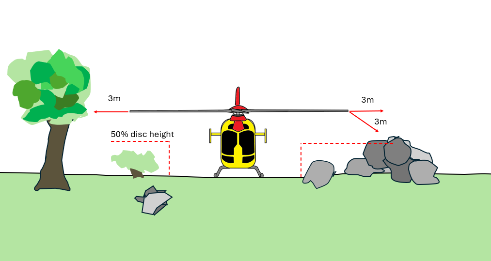
This will look quite familiar from what we have looked at so far. Effectively its what UK operators have to do to interpret the current regulations but given a bit more structure by the regulation. It also risk assessment so the minimum distances could be increased for degraded environments (eg recirculating snow or dust.
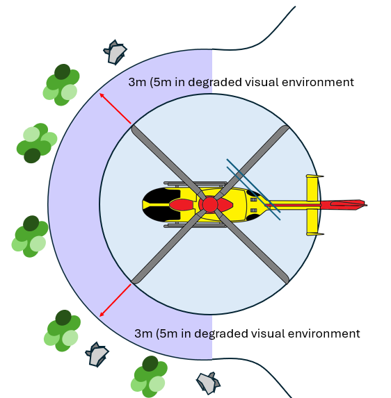
Judging separation from the tips is a trainable skill. This has been done successfully by the UK military for years. Is this a more practical method for HEMS operators whilst still retaining the requirement for 2D for pre-surveyed sites (see regulatory extract above).
Summary
The regulatory requirement of needing a 2D site by day and a 2D x 4D site by night are clear. How to apply these rules needs some careful guidance from operators. When the pilot is eyeballing a site is not the time for asking what 2D means. The only question should be “2D or not 2D”. Or in the case of EASA – something else entirely!
Why not take a look at some of my other blog posts:
- Keeping up with the Norwegians – Six amazing innovations for UK HEMS
- LNAV/VNAV (SBAS) – Are they approved for use in the UK?
- Helicopter 2D IFR approaches – Is CDFA the best choice?
- Understanding Helicopter Flight Manuals – Everything you need to operate safely

- Post Maintenance Flight Tests – How to avoid fatal traps

- First Limit Indicators in Helicopters – Deadly mistakes to avoid
- Bad Vibes – How to report vibrations on helicopters

- Autopilots, cross-checks and low G in helicopter unusual attitude recovery
- Expert site surveys – Improving the assessment of onshore landing areas

- Lights, helipad, action! The problem with new helicopter pad lights
Leave a Reply