

The UK CAA have developed a lighting scheme for hospital helipads in CAP 1264 which is based on the standard for offshore helicopter landing site marking. This offshore scheme is published in CAP 437 and is based on hard won lessons in safely operating helicopters to offshore helidecks (see here) and the principles outlined in ICAO Annex 14 Volume II and ICAO Doc 9261 (the Swiss share these documents here and here). Several hospital helipads have now begun using the lighting scheme after recent upgrades but several issues have arisen with the lights themselves and the associated markings.
In this article we look at the lighting scheme and the problems that have occurred and ask if changes need to happen before any further implementation occurs. Also take a look at our previous article on the issues with the “design” helicopter for these pads here.
Contents
Offshore Helipad Lighting
First, we have to look at the offshore helipad lighting scheme to understand where the onshore scheme was derived from. In the offshore environment at night, crews are operating fairly large helicopters which are predominantly fitted with wheeled undercarriage. Operating to a night deck is challenging with a sharp transition from a very dark, predominantly IFR environment to a mass of lights at the rig in VFR. To prevent confusion and disorientation, a clear, standardised lighting scheme is required to allow crews to safely land.
In many cases, the approach to such a landing site is made to an offset position to allow for a flyaway, giving even higher priority to a good spread of lighting for orientation and conspicuity of the pad in the transition sidewards onto to the deck.
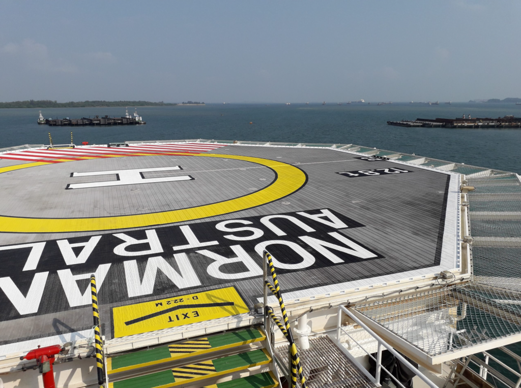
From these driving requirements, the typical scheme is as shown below. It eliminates white edge floodlighting which has been shown to cause glare and leaves a “black hole” in the centre of the pad. It comprises:
- Perimeter lights in green
- A Touch Down Positioning Marking (TDPM) in yellow
- An “H” in green in the centre of the TDPM.
There are slight variations to this scheme – see CAP 437.
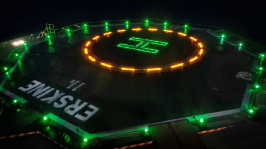
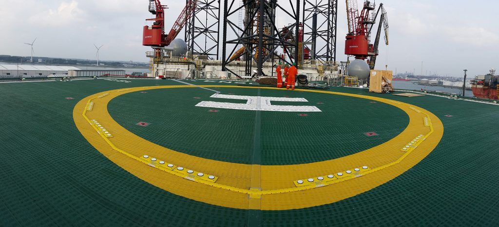
The lights are generally low profile lighting domes for the perimeter lights. For the TDPM and H, the lighting units are generally attached to the surface in units which protrude less than 25mm above the deck with chamfered edges. See example below:
The new lighting scheme is now mandatory in many offshore areas. It helps offshore pilots land safely. Why not apply these lessons to onshore helipads?
Onshore Helipad Lighting
Before the offshore scheme could be applied to onshore pads, the CAA recognised that the situation was slightly different. Several key differences were identified (see para 4.18 – CAP 1264):
- The point load from skids is potentially higher than from a rubber inflated wheel
- Skidded helicopters might caught on raised lights leading to dynamic rollover
- Skidded helicopters might experience ground resonance due to incomplete contact with the ground due to skids resting partially on the raised lights
- Many onshore pads are associated with hospitals where patients are transferred via wheeled trolleys which would be impeded by the raised lighting installations
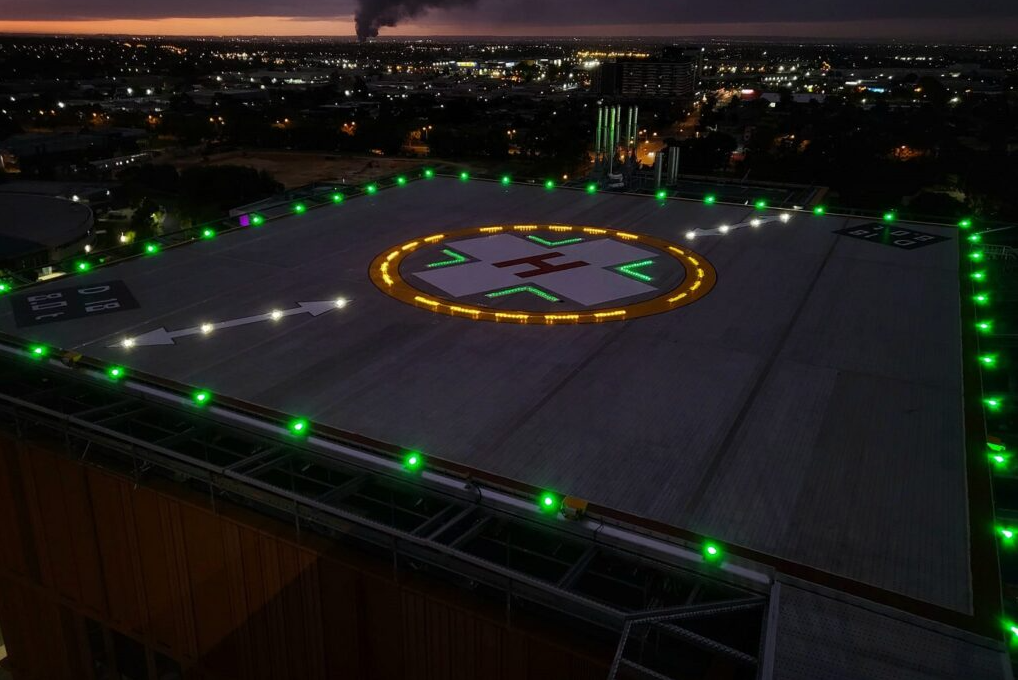
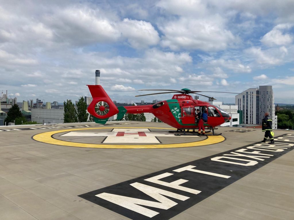
With these issues in mind, the illuminated H of the offshore scheme was replaced with “chevrons” around the cross symbol on the pad and sufficient “gaps” were allowed in the circle of lights at the TDPM. An example of the onshore scheme for hospitals is shown below. Note the gaps on the edge of the TDPM which are aligned with the axes of the cross.
So what is the issue? We get beautifully illuminated helipads and we have factored in all the issues. Or has something been missed? First we need to look at what a TDPM actually is.
Touch Down Positioning Marking (TDPM)
Theory
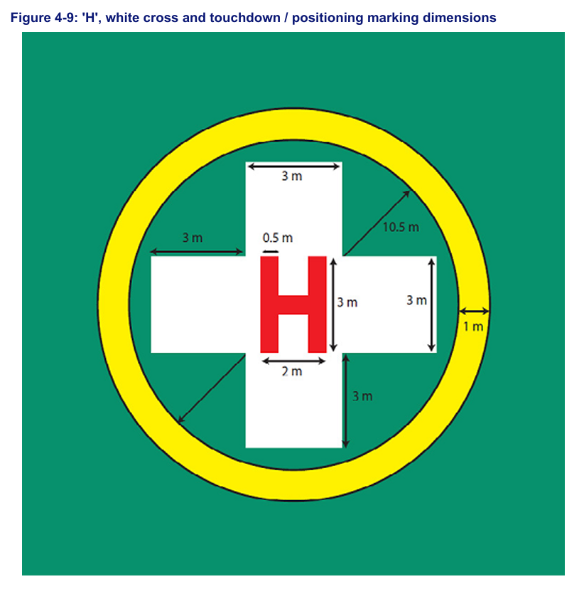
The TDPM is a marking, often a circle, which represents the landing area on a helipad. In the onshore marking scheme in CAP 1264, it is a circle with an inner diameter of 10.5 m (oddly specific isn’t it? – we will revisit this!). The circle itself is 1 m wide. See the diagram below.
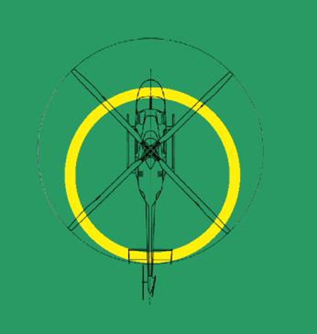
What is not explained at all in CAP 1264 is what the TDPM is actually for. Fortunately ICAO Annex 14 Vol II has the answer (ICAO Annex 14 Vol II):
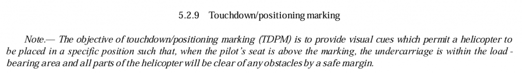
So the TDPM is a very specific symbol. It is sized for the largest helicopter that will use the site (the “design” helicopter – see my article here about how choosing a single design helicopter is not the right path) and the inner diameter of the circle is 0.5D. Thus if a pilot lands using the TDPM as a “bum line” with the helicopter behind them inside the circle, the helicopter wheels should be on a firm footing and the tail is clear of obstacles. If this isn’t possible in some sectors then a hashed area can be marked to prohibit landings in that orientation. Note the obstacle is the opposite side of the circle to the hashed markings. See the example below.
CAP 1264 Interpretation
As already mentioned above, CAP 1264 does not mention how the TDPM is intended to be used and also skips the ICAO derived sizing requirement of 0.5D for the design helicopter. Instead in the “…interests of standardisation…” CAP 1264 standardises the sizing requirement for the TDPM as 10.5 m inner diameter:
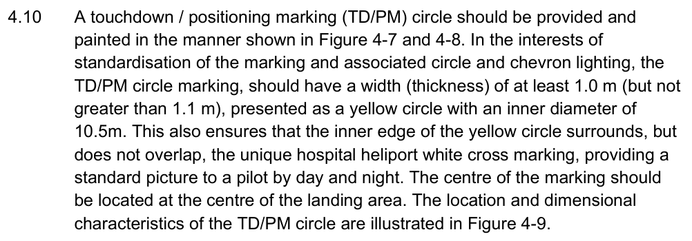
Of note, the oddly specific 10.5 m requirement actually aligns with 0.5 D for an S92A. So all onshore pads have a TDPM that is too big for the vast majority of onshore aircraft
In Practice
As already mentioned, the TDPM is intended to be used as a positioning marker by the pilot, with the pilot landing on the edge of the circle as shown below:
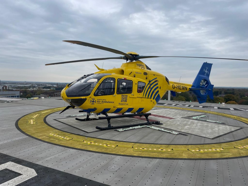
With the oversize TDPM for onshore pads, this looks like this for a typical UK HEMS helicopter:
Whereas a correctly sized TDPM makes a lot more sense.
Look closely at the positioning of the skids in both cases above. On the EC135 and other similar aircraft, the skids extend to a point in line with the pilot’s “bum line”. If the pilot lands in accordance with ICAO guidance the skids are on the TDPM. Remember the light scheme? The skidded aircraft will now land on the raised TDPM lights, potentially leading to the ground resonance, dynamic rollover and point load issues that the CAP 1264 was designed to avoid.
Normalisation of Deviance
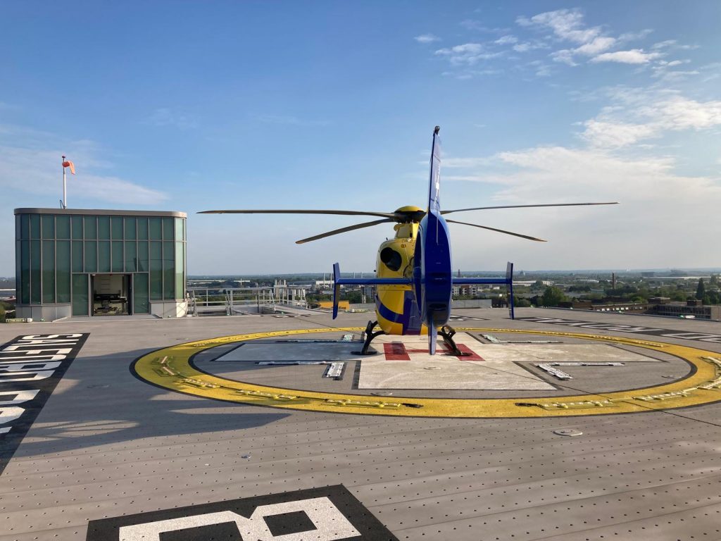
How could a lighting scheme miss this obvious issue? Pilots land using the TDPM circle all the time! Surely this was picked up?! Except of course, that is not how many onshore pilots use the circle due to a lack of knowledge about the true reason for the TDPM (the Senior Rotary Geek included). As an example, the typical positioning of a UK helicopters on an onshore helipad are shown below:
Pilots just land in the middle on the H! Due to the size of the TDPM being set for an S92A, it is unlikely that this mis-positioning will cause any harm – right up to the point where this normalisation of deviance leads to the tail being further back that the designer intended. In particular this could occur at a non-standard pad which is sized for a smaller machine and obstacles such as windsocks may be placed as to cause a hazard.
The normalisation of deviance of landing in the centre of the circle has the potential to lead to errors and mistakes and should be addressed by the regulator. Perhaps the TDPM is renamed or its intended use clarified in regulation?
Chevrons
Theory
Moving on to the chevrons. The H is not lit in the onshore scheme to avoid issues of skids landing on the lights. Instead chevrons around the cross symbol are outlined in CAP 1264 as shown below:
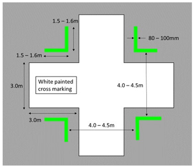
This leaves ample space for the pilot to land in between the markings (provide the pilot deviates from ICAO of course!). An EC135 has a skid width of 2 m, so comfortably slotting in nicely. The H145 is 2.4 m so also no problem. The Bell 429 is a slightly more chunky 2.67 m giving less flexibility. Once landed and provided the pilot has aligned with the cross, there are convenient gaps to roll in a trolley from the side to offload a patient. In the example below, the trolley can approach without hitting the lights from the 9 o’clock directly to the left door for offloading.
On an H145 where the patient is offloaded from the tail, there will be a similar flat path to the aircraft.
So the pilot is now constrained to 4 possible landing directions due to the new lighting scheme. We seem to be deviating from the key principle of a hospital helipad – the needs of the patient. Forcing a pilot to manoeuvre in a critical stage of flight to align with lighting installations seems to go against this. But more importantly, what about during a reject from an engine failure? What would be the result of a rejected takeoff landing on the lights? Dynamic rollover in the worst case!
Alignment problems
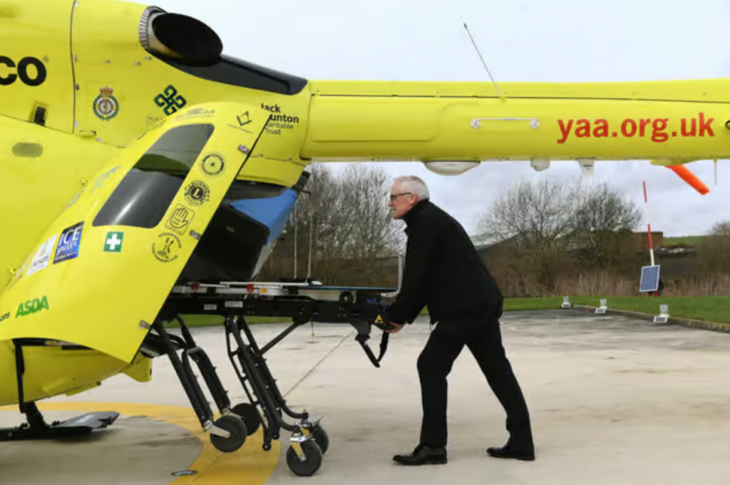
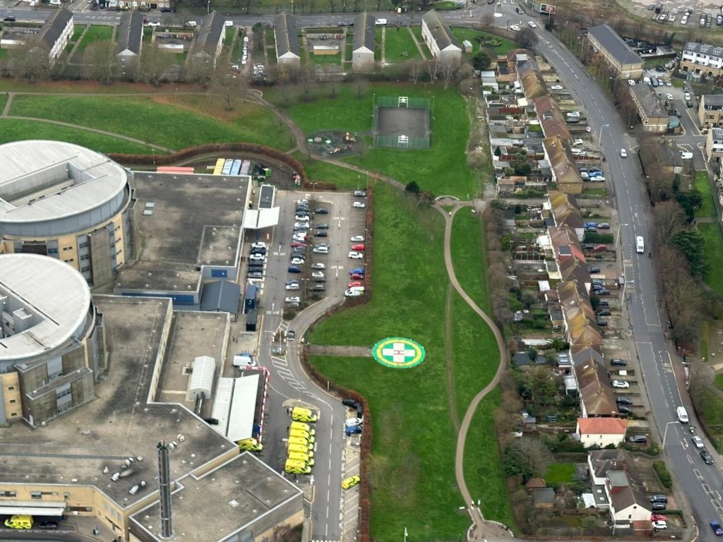
The problems do not end there. The assumption is that the patient will be extracted at 90 degrees to the longitudinal axis. Unfortunately on some machines that is not the case. On the EC135, due to the articulation of the stretcher system, the patient is actually extracted at a more acute angle. As shown in the example below, the hospital trolley is canted towards the front of the helicopter and would have to mount the lighting system to do so. Note the typical small wheels on this particular trolley – a 25 mm step would cause issues.
So does the pilot now land aligned to the cross or diagonally to align the normal stretcher extraction path with the gaps in the lighting? The chevrons are not helping the patient here!
Choices
Whilst for elevated pads, the chevrons are mandatory as part of the scheme, it is optional for ground based helipads.
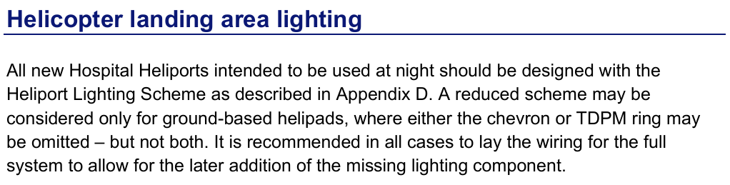
This option to choose only one of TDPM or chevron lighting has been selected by several recently upgraded pads in the UK (eg Queens Hospital Romford, Essex as shown below. This exemption allows for all of the identified issues with the chevron marking to be avoided. Should the chevrons be optional for the elevated pads too?
Drive behind new lighting
Lets go back to the beginning for a moment. The reason the new lighting scheme was brought in offshore was due to the sharp transition in lighting environment during approaches, the poor lighting of the pad by floodlights and the need for adequate orientation references. This led to a lighting requirement in the centre of the pad (the TDPM and the lit H). The lighting was designed to be used when the pilot was approaching the pad, typically to one side.
This requirement does not translate well to onshore operations using Cat A helipad or vertical profiles. In onshore profiles, particularly with more modern machines, the approaches and departures are steep or vertical. Typically this leads to significant parts of the landing area and associated lighting being obscured by the airframe or by camera limitations
For this reason, wider markers are more useful in positioning. By day, pilot selected markers beyond the pad can be used for alignment and reference. By night, this is much more challenging, particularly as the landing site goes under the aircraft in the latter stages of the approach. What would be really helpful is lights outside the TDPM for alignment. Perhaps in place of chevrons there could be a cross outside the TDPM or approach path markers. This latter option is listed in CAP 1264 but is currently hidden as a sub-para of the Obstructions section. Remember the example of Victorian Heart Hospital, Melbourne?
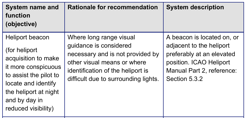
As mentioned above the paragraph regarding these lights is hidden in CAP 1264 at para 4.25 but is worth considering for future pads:
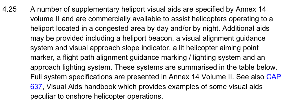
Missed opportunity – The Heliport Beacon
As an aside, due to the mis-labelled paragraph above, one key option for hospital helipads has not been emphasized enough in CAP 1264 – the Heliport Beacon. This is present at a limited number of UK hospital pads and is incredibly useful for working out if a pad is active and available. The strobing white light can be seen by day and provides a clear indication that the helipad is manned and ready.
This beacon should be a mandatory feature on all helipads with the clear meaning that if (and only if) it is lit, the pad is ready for use (eg security in place). Where no such beacon is present, it is often a confusing game of guessing whether security is in place and whether the right measures are in place for landing. At some sites the pad lighting system is switched on to show the site is open – these lights can be impossible to see in bright sunlight!
Of note, in one unfortunate UK hospital example, the lights were used to indicate the pad was open and security was in place. However, the pilot could control the lighting by radio transmission so the effectiveness of this indication was somewhat negated! The heliport beacon should therefore only be controllable by the heliport management team if used to indicate the pad is open.
Conclusion
Several issues with the lighting system in CAP 1264 have been identified:
- Normalisation of deviance – Pilots are not using the TDPM as intended by ICAO Annex 14 Vol II
- Raised lighting on TDPM/Chevrons can interfere with normal helicopter landings
- Raised lighting installations can interfere with patient transfer by hospital trolley in ways not envisioned in the original design but are mandatory in the current scheme
- The lighting scheme may not be providing the right cues for onshore Cat A profiles
- There is a huge missed opportunity to clearly identify whether helipads are ready for use using a Heliport Beacon, controlled by the heliport team
Hopefully future incremental updates of the CAP 1264 scheme can address these issues.
Take a look at my other articles:
- Unfair Skies: Restrictive helicopter instructor rules and how to fix them
- How to create an instrument rating instructor (IRI) – A helicopter anomaly
- The evolution of Category A Helipad procedures – A strong foundation for VTOL to learn from?
- Strips vs dials – Which is better?
- Under the weather – are UK HEMS weather rules broken?
Leave a Reply